
Summary of Contents for Transmitter Solutions RCMMOD
- Page 1 NO TOUCH ADA ACCESS RETROFIT MODULE Retrofit Contactless Module (RCM) Two Wire Module (TWM) RCMMOD TWMMOD 866.975.0101 • 866.975.0404 www.transmittersolutions.com...
-
Page 2: Specifications
Package • Retrofit Contactlesss Module - 1 • Two Wire Module - 1 • Expansion Screws 4*20mm - 4 • Screw M3*20mm - 4 • Double Sided Adhesive 43x31x1mm - 2 • Acetate Cloth Tape 55x40x0.15mm - 1 • Installation and Operation Manual - 1 Specifications Retrofit Contactless Module Operating Voltage... -
Page 3: Installation
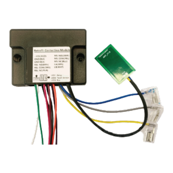
Installation • Wiring all wires to the correct place. • Fix the screws as shown in figure 1. • Wiring the wires to the mechanical switch as shown in figure 2. • Attach the antenna to the metal plate as shown in figure 3. •... - Page 4 Retrofit Contactless Module Definition Connector Connect to door controller Connect to TWM(Master) Antenna Connect to Mechanical Switch JP1 Wiring +12/24V Power Supply BLACK Ground BLACK Ground BROWN RELAY_NO Relay Output - Normal Open ORANGE RELAY_COM Relay Output - Common PURPLE RELAY_NC Relay Output - Normal Close JP2 Wiring...
- Page 5 Two Wire Module Connector Definition Connect to door controller onnect to TWM(Slave) embedded in RCM JP5 Wiring +12/24V Power Supply BLACK Ground BLACK Ground BROWN RELAY_NO Relay Output - Normal Open ORANGE RELAY_COM Relay Output - Common PURPLE RELAY_NC Relay Output - Normal Close JP6 Wiring GREEN Communication Bus - LA...
-
Page 6: Wiring Diagrams
Wiring Diagrams Normal Mode: +VDC REL_COM REL_NO/NC Door Controller • Retrofit Contactless Module directly connects to door controller. • Put your hand near the button then you will trigger the device. The relay inside the device will trigger for 1 second, and the buzzer will beep once. •... - Page 7 Wiring Diagrams Normal Mode: +VDC REL_COM REL_NO/NC Door Controller • Retrofit Contactless Module works with Two Wire Modules. Only two wires are needed for both power supply and data communication. • Put your hand near the button then you will trigger the device, and the buzzer will beep once.
- Page 8 866.975.0101 • 866.975.0404 www.transmittersolutions.com...
Need help?
Do you have a question about the RCMMOD and is the answer not in the manual?
Questions and answers