
Related Manuals for GUSHER PUMPS 32-125

Summary of Contents for GUSHER PUMPS 32-125
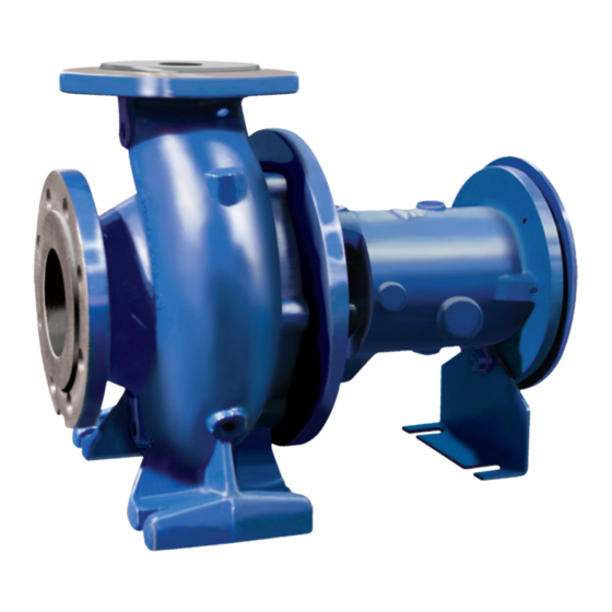
- Page 1 DIN STANDARD HORIZONTAL END SUCTION CENTRIFUGAL PUMP SERIES Installation, Operation and Maintenance Manual...
-
Page 2: Table Of Contents
Table of Contents Operating and Service Manual for DIN END SUCTION CENTRIFUGAL PUMP SERIES FOREWORD ............GENERAL INFORMATION ........RECEIVING AND INSPECTION ....... INSTALLATION ..........OPERATION ............. DRAWINGS DIN 1 POWER FRAME ......DIN 2 -3 POWER FRAME ......PACKING SEAL ........ -
Page 3: Operating And Service Manual For Din End Suction Centrifugal Pump Series
Further instructions concerning the components of the pump must be observed. WARRANTY Gusher Pumps, Inc. will replace or repair at our discretion, within one year of shipment from our plant, any pump in our judgement that has failed due to defects in materials or workmanship, provided the pump has been properly installed and maintained and has not been subjected to abuse. -
Page 4: General Information
Wear Rings Renewable carbon wear rings. Shaft Sleeve - Renewable Shaft Sleeve 3 POWER FRAME SIZES: eases maintenance (easily removed) MODELS WITH DIN 1 POWER FRAME and is releaved to allow for changes 32-125 32-160 32-200 32-250 in temperature. 40-125 40-160... -
Page 5: Receiving And Inspection
Receiving and Inspection Gusher Pumps, Inc. has taken great care 4. Pump suction and discharge points must in preparing your pump for shipment, be covered to prevent foreign material However, due to circumstances beyond from getting into the pump and causing... -
Page 6: Installation
Installation PREPARATION When preparing your pump for bearing housing. The bearing housing must installation, the discharge and suction then be thoroughly cleaned with kerosene ports must be clean and free of anything or carbon tetrachloride and relubricated. that might prohibit a tight connection. This is not required on sealed for life bearings. - Page 7 Installation SYSTEM PIPING Guidelines for piping are given in the 4). Liquid coming back into the resevoir “Hydraulic Institute Standards” available should not enter near the pump suction from the Hydraulic Institute, 30200 Detroit pipe and the liquid should not drop Road, Cleveland, OH 44145-1967.
-
Page 8: Operation
Operation PREPARATION FOR START-UP Check Rotation Couple Pump and Motor 1). Wire the motor according to motor 1). Lock out power to motor to prevent accidental rotation and physical injury. manufacturers speci cations and according to state and local 2). Install and lubricate coupling per regulations. - Page 9 Operation OPERATION 3). Drain all liquid from inside of the pump 5). To prevent damage from cavitation or if it will be exposed to freezing conditions recirculation, always operate pump at or while idle. The conditions could cause near rated conditions. liquid to freeze and damage the pump.
-
Page 10: Din 1 Power Frame
Power Frame 1 DIN 1 (SMALL) POWER FRAME Models for DIN 1 32-125 32-160 32-200 32-250 40-125 40-160 40-200 40-250 50-125 50-160 50-200 50-250 65-125 65-160 65-200 65-250 Part Part Number Description Number Description Bearing Retainer Gasket Ball Bearing Mechanical Seal... -
Page 11: Din 2 -3 Power Frame
Power Frame 2 & 3 DIN 2 & 3 (LARGE) POWER FRAME Models for DIN 2 Models for DIN 3 40-315 50-315 65-250 80-400 100-400 125-315 125-400 150-315 150-400 65-315 80-200 80-250 80-315 100-160 100-200 100-250 100-315 125-200 125-250 150-200 150-250 Part Part... -
Page 12: Packing Seal
1...Cartridge Seal 2...Packing 3...Packing Seat Washer 2...Gasket For all other parts descriptions, refer to pages 10 and 11 This illustration is for reference only. Your product may vary. Please consult with Gusher Pumps for any other information you may require. -
Page 13: Closed Coupled Style
CDM STYLE Number Description: 1...Motor 2...Barrel 3...Coupling For all other parts descriptions, refer to pages 10 and 11 This illustration is for reference only. Your product may vary. Please consult with Gusher Pumps for any other information you may require. -
Page 14: Malfunctions / Causes
Troubleshooting and Spare Parts MALFUNCTIONS / CAUSES Malfunction Cause Pump not lled, tubing not deaired Speed too low Speed too high Suction line leaky Air or gas lock in the pumping medium Counterpressure too high Suction head too high Feed pressure too low with hot pumping medium Tubing on suction side not su ciently covered with liquid Density of pumping medium too high Viscosity of pumping medium too high... -
Page 15: Pump Tips
Pump Tips COUPLING GUARDS MAINTENANCE SAFETY Never operate a pump without coupling Never apply heat to remove impeller. guards properly installed. Always lockout power. CONNECTIONS Ensure pump is isolated from the Never force piping to make connection system and pressure is relieved before with a pump. - Page 16 Ruthman Companies: A family-owned business supplying pumps for over 100 years coining the term ‘coolant pump.’ The brothers named this Ruthman Companies was co-founded in 1912 by brothers brand, Gusher Pumps. Alois and Edward Ruthman as the “Ruthman Machinery Company.” Based in Cincinnati, the company serviced the Alois’...
Need help?
Do you have a question about the 32-125 and is the answer not in the manual?
Questions and answers