Table of Contents
Advertisement
Quick Links
Advertisement
Table of Contents

Related Manuals for Tekron TCG 01-G

Summary of Contents for Tekron TCG 01-G
- Page 1 TCG 01-G USER MANUAL Sixth Edition – Copyright ©2021...
-
Page 2: Table Of Contents
© 2021 by Tekron International Limited. All Rights Reserved. All trademarks are the property of their respective holders. The information in this document is provided for informational use only and is subject to change. For further information or support,... - Page 3 © 2021 by Tekron International Limited. All Rights Reserved. All trademarks are the property of their respective holders. The information in this document is provided for informational use only and is subject to change. For further information or support,...
- Page 4 © 2021 by Tekron International Limited. All Rights Reserved. All trademarks are the property of their respective holders. The information in this document is provided for informational use only and is subject to change. For further information or support,...
-
Page 5: Introduction
© 2021 by Tekron International Limited. All Rights Reserved. All trademarks are the property of their respective holders. The information in this document is provided for informational use only and is subject to change. For further information or support,... -
Page 6: Configuration
© 2021 by Tekron International Limited. All Rights Reserved. All trademarks are the property of their respective holders. The information in this document is provided for informational use only and is subject to change. For further information or support,... -
Page 7: Front Panel
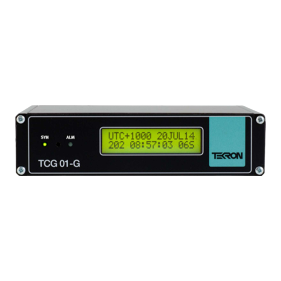
2. FRONT PANEL Figure 2 – TCG 01-G front panel TCG 01-G features two LED indicators on the front panel (Figure 2), together with a 2-line by 16- character backlit LCD display. SYN LED: This LED shows the status of the current sync source. - Page 8 © 2021 by Tekron International Limited. All Rights Reserved. All trademarks are the property of their respective holders. The information in this document is provided for informational use only and is subject to change. For further information or support,...
- Page 9 © 2021 by Tekron International Limited. All Rights Reserved. All trademarks are the property of their respective holders. The information in this document is provided for informational use only and is subject to change. For further information or support,...
-
Page 10: Contrast Adjustment Mode
© 2021 by Tekron International Limited. All Rights Reserved. All trademarks are the property of their respective holders. The information in this document is provided for informational use only and is subject to change. For further information or support,... -
Page 11: Led Indicators
© 2021 by Tekron International Limited. All Rights Reserved. All trademarks are the property of their respective holders. The information in this document is provided for informational use only and is subject to change. For further information or support,... -
Page 12: Alarm Messages
© 2021 by Tekron International Limited. All Rights Reserved. All trademarks are the property of their respective holders. The information in this document is provided for informational use only and is subject to change. For further information or support,... -
Page 13: Back Panel
© 2021 by Tekron International Limited. All Rights Reserved. All trademarks are the property of their respective holders. The information in this document is provided for informational use only and is subject to change. For further information or support,... -
Page 14: Back Panel - Inputs And Outputs
Antenna Cable Considerations: The Tekron antenna port expects a signal with at least 15 dB of gain, and no more than 35 dB of gain, with 20-35 dB being the optimal gain range. The Tekron supplied antenna delivers 40 dB of gain into the antenna cable, hence the loss of the antenna cable in the installation should fall within the ranges specified below. - Page 15 © 2021 by Tekron International Limited. All Rights Reserved. All trademarks are the property of their respective holders. The information in this document is provided for informational use only and is subject to change. For further information or support,...
-
Page 16: P2, P3: Programmable Outputs (2-Pin [3.81 Mm] / Bnc Or St Fiber)
© 2021 by Tekron International Limited. All Rights Reserved. All trademarks are the property of their respective holders. The information in this document is provided for informational use only and is subject to change. For further information or support,... -
Page 17: P4: Serial Port And Programmable Output (Db9 Connector)
© 2021 by Tekron International Limited. All Rights Reserved. All trademarks are the property of their respective holders. The information in this document is provided for informational use only and is subject to change. For further information or support,... -
Page 18: P4 Pin 1 Programmable Output
Simulated DCF77 receiver time code. Refer to the Tekron Configuration Tool Manual for further information. P4 pin 1 is not available on TCG 01-G with DTE serial port. If not specified, TCG 01-G will ship with a DCE serial port. -
Page 19: P6: Event Recording / Irig-B Sync Inputs (4-Pin 3.81 Mm Connector)
© 2021 by Tekron International Limited. All Rights Reserved. All trademarks are the property of their respective holders. The information in this document is provided for informational use only and is subject to change. For further information or support,... -
Page 20: Admin/Eth1: Ethernet Communication Port (Rj-45 Connector)
© 2021 by Tekron International Limited. All Rights Reserved. All trademarks are the property of their respective holders. The information in this document is provided for informational use only and is subject to change. For further information or support,... -
Page 21: Software
© 2021 by Tekron International Limited. All Rights Reserved. All trademarks are the property of their respective holders. The information in this document is provided for informational use only and is subject to change. For further information or support,... -
Page 22: Installation
Mounting the TCG 01-G The TCG 01-G can be used free-standing or mounted in a 19” rack. Each unit ships with a rack- mount bracket which can be attached by removing the 4 corner front panel screws and attaching the plate as illustrated in Figure 9. - Page 23 © 2021 by Tekron International Limited. All Rights Reserved. All trademarks are the property of their respective holders. The information in this document is provided for informational use only and is subject to change. For further information or support,...
-
Page 24: Event Recording Function
TCG 01-G is connected to; is turned OFF, wait a full ten seconds, and then turned ON again. This will result in the TCG 01-G having to resynchronize with the GNSS satellites. - Page 25 © 2021 by Tekron International Limited. All Rights Reserved. All trademarks are the property of their respective holders. The information in this document is provided for informational use only and is subject to change. For further information or support,...
-
Page 26: Factory Reset
© 2021 by Tekron International Limited. All Rights Reserved. All trademarks are the property of their respective holders. The information in this document is provided for informational use only and is subject to change. For further information or support,... -
Page 27: Factory Hardware Options
High Voltage (MOSFET) Output Option The TCG 01-G may be ordered with either or both of the P2 and P3 outputs configured with a high voltage FET switching transistor instead of the standard 5 V logic output. When fitted in this manner, each output can switch a 300 V DC, 100 mA external load. -
Page 28: Lightning Protection Option
© 2021 by Tekron International Limited. All Rights Reserved. All trademarks are the property of their respective holders. The information in this document is provided for informational use only and is subject to change. For further information or support,... -
Page 29: Installation
© 2021 by Tekron International Limited. All Rights Reserved. All trademarks are the property of their respective holders. The information in this document is provided for informational use only and is subject to change. For further information or support,... -
Page 30: Appendix
© 2021 by Tekron International Limited. All Rights Reserved. All trademarks are the property of their respective holders. The information in this document is provided for informational use only and is subject to change. For further information or support,... -
Page 31: Environmental Specifications
© 2021 by Tekron International Limited. All Rights Reserved. All trademarks are the property of their respective holders. The information in this document is provided for informational use only and is subject to change. For further information or support,... - Page 32 © 2021 by Tekron International Limited. All Rights Reserved. All trademarks are the property of their respective holders. The information in this document is provided for informational use only and is subject to change. For further information or support,...
- Page 33 © 2021 by Tekron International Limited. All Rights Reserved. All trademarks are the property of their respective holders. The information in this document is provided for informational use only and is subject to change. For further information or support,...
-
Page 34: Serial Output Strings
© 2021 by Tekron International Limited. All Rights Reserved. All trademarks are the property of their respective holders. The information in this document is provided for informational use only and is subject to change. For further information or support,... -
Page 35: Irig J-17 Time Code O/P On P4
© 2021 by Tekron International Limited. All Rights Reserved. All trademarks are the property of their respective holders. The information in this document is provided for informational use only and is subject to change. For further information or support,... -
Page 36: String-A Time Code O/P On P4
© 2021 by Tekron International Limited. All Rights Reserved. All trademarks are the property of their respective holders. The information in this document is provided for informational use only and is subject to change. For further information or support,... -
Page 37: String-B Time Code O/P On P4
© 2021 by Tekron International Limited. All Rights Reserved. All trademarks are the property of their respective holders. The information in this document is provided for informational use only and is subject to change. For further information or support,... -
Page 38: String-C Time Code O/P On P4
© 2021 by Tekron International Limited. All Rights Reserved. All trademarks are the property of their respective holders. The information in this document is provided for informational use only and is subject to change. For further information or support,... -
Page 39: String-D Time Code O/P On P4
© 2021 by Tekron International Limited. All Rights Reserved. All trademarks are the property of their respective holders. The information in this document is provided for informational use only and is subject to change. For further information or support,... -
Page 40: String-E Time Code O/P On P4
© 2021 by Tekron International Limited. All Rights Reserved. All trademarks are the property of their respective holders. The information in this document is provided for informational use only and is subject to change. For further information or support,... -
Page 41: String-F Time Code O/P On P4
© 2021 by Tekron International Limited. All Rights Reserved. All trademarks are the property of their respective holders. The information in this document is provided for informational use only and is subject to change. For further information or support,... -
Page 42: String-G Time Code O/P On P4
© 2021 by Tekron International Limited. All Rights Reserved. All trademarks are the property of their respective holders. The information in this document is provided for informational use only and is subject to change. For further information or support,... - Page 43 © 2021 by Tekron International Limited. All Rights Reserved. All trademarks are the property of their respective holders. The information in this document is provided for informational use only and is subject to change. For further information or support,...
-
Page 44: String-H Time Code O/P On P4
© 2021 by Tekron International Limited. All Rights Reserved. All trademarks are the property of their respective holders. The information in this document is provided for informational use only and is subject to change. For further information or support,... -
Page 45: Nmea Zda Time Code O/P On P4
© 2021 by Tekron International Limited. All Rights Reserved. All trademarks are the property of their respective holders. The information in this document is provided for informational use only and is subject to change. For further information or support,... -
Page 46: Nmea Rmc Time Code O/P On P4
© 2021 by Tekron International Limited. All Rights Reserved. All trademarks are the property of their respective holders. The information in this document is provided for informational use only and is subject to change. For further information or support,... -
Page 47: Irig-B Specification
© 2021 by Tekron International Limited. All Rights Reserved. All trademarks are the property of their respective holders. The information in this document is provided for informational use only and is subject to change. For further information or support,... -
Page 48: Event Recording Specification
Time tags use UTC time, and each tag includes the year, day of year, hour, minute and second, as well as fraction of second to a resolution and accuracy of 100 ns. The TCG 01-G measures time internally in 40 ns intervals, rounding to the nearest 100 ns for time tag storage purposes, thus allowing accuracy to equate to resolution. -
Page 49: Tcg 01-G Commands Related To Event Time Tagging
© 2021 by Tekron International Limited. All Rights Reserved. All trademarks are the property of their respective holders. The information in this document is provided for informational use only and is subject to change. For further information or support,... -
Page 50: Notes Concerning The Ps Command
© 2021 by Tekron International Limited. All Rights Reserved. All trademarks are the property of their respective holders. The information in this document is provided for informational use only and is subject to change. For further information or support,... -
Page 51: Pr Command: Repeat Last Tag Sent
© 2021 by Tekron International Limited. All Rights Reserved. All trademarks are the property of their respective holders. The information in this document is provided for informational use only and is subject to change. For further information or support,... -
Page 52: Warranty
© 2021 by Tekron International Limited. All Rights Reserved. All trademarks are the property of their respective holders. The information in this document is provided for informational use only and is subject to change. For further information or support,...
Need help?
Do you have a question about the TCG 01-G and is the answer not in the manual?
Questions and answers