
Summary of Contents for Blohm + Voss Oil Tools 9PU-7200
- Page 1 Blohm + Voss Oil Tools, LLC Hydraulic Power Unit 9PU-7200 Technical Documentation...
- Page 2 Blohm + Voss Oil Tools, LLC. Manufacturer & Agents World Wide Blohm + Voss Oil Tools Blohm + Voss Oil Tools, LLC Premier Sea & Land Pte. Ltd. 7670 Woodway, Suite 266 Houston, Texas Shaw Centre Hermann-Blohm-Straße 2...
- Page 3 Safety Issues WARNING: FAILURE TO (SLINGS, CABLES, WARNING: ONE SHOULD CONDUCT ROUTINE WARNING: KEEP HANDS SHACKLES AND THE AVOID CREATING IGNITION MAINTENANCE COULD AND ARMS CLEAR OF LIKE) THAT HAVE BEEN SOURCES, LIKE HEAT, AS A RESULT IN EQUIPMENT ALL MOVING PARTS INSPECTED AND ARE IN RESULT OF THE USE OF THE DAMAGE OR INJURY TO...
-
Page 4: Table Of Contents
TABLE OF CONTENTS TABLE OF CONTENTS DESCRIPTION General Components Motor Hydraulics Tank Filters Cooler/Heater Explosion Proof Box Specifications Location of Identification Tag Hydraulic Specifications Shipping Data COMMISSIONING FloorHand Commissioning Procedure Record of Training INSTALLATION Lifting Electrical Attaching the Hydraulic Lines Filling the Reservoir OPERATIONS Start-up procedure... -
Page 5: Description
DESCRIPTION... -
Page 6: General Components
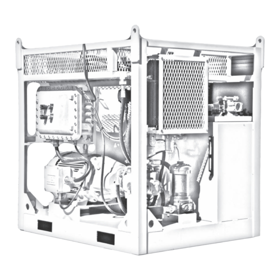
General Components All components of the Hydraulic Power Unit are mounted within a rugged but lightweight frame. The components are mounted with consideration for easy access during operation, maintenance and repair. The Hydraulic Power Unit utilizes a pressure compensated hydraulic pump close-coupled to an electric motor. -
Page 7: Cooler/Heater
Cooler/Heater Depending on your location, Blohm+Voss will have either an oil cooler or a heater built into the unit. Explosion Proof Box The electical system on the hydraulic power unit is a self contained and requires only a power connection between the motorstarter box and the rig generator house or other appropriate electric power source. -
Page 8: Hydraulic Specifications
Hydraulic Specifications Hydraulic pressure: Operating: 2,500 PSI (17,236 kPa) Maximum: 3,400 PSI (23,443 kPa) Hydraulic flow: Operating: 26 GPM (98.42 Liters) Pressure Line Connection: 1” Male JIC Return Line Connection: 1 1/4” Male JIC Electrical Horsepower: 40 HP @ 60 Hz Electrical power required: 50 amps, 440 volt, 3 Phase Pressure and Return Filters:... -
Page 9: Commissioning
COMMISSIONING... - Page 10 Approved: Suppiler References: Procurement References: TAG No: Date: Signature: SDRL Code: Area: System: Pages: Encl: Company: Document Title/ Equipment: Commissioning Check Sheet for FloorHand (Iron Roughneck) Rig/Vessle/Customer Order: Equipment Serial No: Supplier: Document No: Blohm + Voss Oil Tools, LLC...
-
Page 11: Floorhand Commissioning Procedure
Note: spinner may, or may not close evenly, this is normal. ___ Back torque adjustment knob out completely, then turn in (clockwise) 4 turns, Blohm + Voss Oil Tools, LLC. ___ Actuate torque cylinder 10 complete strokes in each direction and check for leaks. - Page 12 cylinder. Verify during commissioning. ___ Clamp upper wrench, ensure that system pressure is now present on lower clamp cylinders also (PRV reading should not change), unclamp upper wrench, unclamp lower wrench. ___ Mock up test pipe, with torque, at end of stroke, check that gauge dump valve functions correctly.
-
Page 13: Record Of Training
Date: (Lubrication/Frequency/PM,etc.) My signature above indicates that I have read and understand the opening instructions and have been trained to use the above machine by Blohm + Voss Oil Tools, LLC Technicians. Acknowledgement of Rig Superintendant / Tool Pusher Date... -
Page 14: Installation
INSTALLATION... -
Page 15: Lifting
Lifting The Hydraulic Power Unit frame incorporates lifting lugs on the uppermost corners of the frame. The unit should always be lifted using a four point sling with equal length legs, one leg of the bridle attached to each of the brackets. The hose basket and lifting frame is designed to support hoses and cables with a combined weight not to exceed 250 lbs. -
Page 16: Attaching The Hydraulic Lines
Attaching the Hydraulic Lines Remove cap or plug and ensure that mating parts of the hydraulic connection are clean and free from dirt or other contaminants. Carefully thread the connection together and tighten appropriately. Filling the Reservoir The reservoir is filled via the breather connection on the top of the reservoir. Conventional petroleum based hydraulic fluid is usually specified but care should be taken to ensure that it is compatible with the environment it will be operated in, particularly for the ambient tem- perature range. -
Page 17: Operations
OPERATIONS... -
Page 18: Start-Up Procedure
There are two pumps incorporated with the Hydraulic Power Unit. The first pump is a large pressure compensated hydraulic pump. Essentially, it is one that senses outlet pressure and adjusts displacement accordingly. The pump has a 3/4” case drain with no restriction. The pump has its own bypass-able, inlet strainer and ball valve. - Page 19 Loosen a fitting in the main hydraulic pump discharge line to allow the air to be bled during the priming procedure. When oil is present at the loosened coupling, and the line is free of air, the coupling may be retightened. Remove the plastic cover that shields the motor coupling.
-
Page 20: Hpu Will Not Power Up
Fill the HPU to minimum troubleshoot the main contactor or connected and turn on the 3/4 up the sight glass. contact Blohm + Voss Oil Tools LLC. breaker. WARNING: MANuALLY OvERRIDING ThE LOW OIL LEvEL ShuT OFF SWITCh BY hOLDING IN ThE CONTACTOR WILL BuRN-OuT ThE CONTACTOR, ThuS vOIDING ANY WARRANTY ON ELECTRICAL COMPONENTS. -
Page 21: Hpu Powers Up, But Will Not Build Pressure
Troubleshooting HPU powers up, but will not build pressure. START Is the HPU Disconnect HPU from any Is HPU Compensator connected to any open centered equipment Valve closed? equipment with open and cap lines. centered valving? Close the Isolate hpu from the rest compensator valve. -
Page 22: Maintenance & Inspection
MAINTENANCE & INSPECTION... -
Page 23: Electric Motors
Electric Motors Electric motors should be lubricated as indicated by the motor manufacturer. Grease zerks are installed, do not over lubricate. Note: It is important to monitor the filters during the initial start-up and during the break-in period. Note: Indicators must be checked while Spinner motors are running. -
Page 24: Spare Parts
SPARE PARTS... -
Page 25: Recommended Spare Parts For One Year Operation
Recommended Spare Parts for One Year Operation Qty/ Item Reference number Description 9PU-8006 DRIVE COUPLING SP3 & 4 9FH-01152-7 HPU MAIN SUCTION STRAINER SP4 & 7 9FH-01152-8 HPU CIRCULATING SUCTION STRAINER 9FH-01152-6 HPU RETURN FILTER ELEMENT 9FH-01152-4 HPU PRESSURE FILTER ELEMENT 9PU-8003 GAUGE 9PU-8005... - Page 26 DRAWINGS...
- Page 27 Figure 9...
- Page 28 Figure 10...
- Page 29 Figure 11...
- Page 30 Figure 12...
- Page 31 Figure 13...
- Page 32 Figure 14 Figure 15...
- Page 33 Figure 16...
- Page 34 Item Part Number Description 9PU-7100FRM HYDRAULIC POWER UNIT FRAME 9AF3X2B BUSHING 9AF2XCLN CLOSE NIPPLE 9FH-01152-7 HPU MAIN SUCTION STRAINER 9AF1X34B BUSHING 9AF34X2N NIPPLE 9FH-01152-8 HPU CIRCULATING SUCTION STRAINER 9AF2XCLN CLOSE NIPPLE 9AF2S90 STREET 90 9PU-8008 BALL VALVE 9PU-8009 BALL VALVE 9HC12HHP COUNTERSUNK PLUG 9PU-8019...
- Page 35 Item Part Number Description 9PU-8020 EXPLOSION PROOF COOLER 9BN0115107 HEX HEAD CAP SCREW 9BN1133815 SAE WASHER 9BN1137185 NYLON LOCK NUT 9FH-01402 HPU TEMP SWITCH MOUNT BRACKET 9PU-8018 EXPLOSION PROOF TEMP SWITCH 9FH-01401 HPU TEMP SWITCH MANIFOLD 9BN0115005 HEX HEAD CAP SCREW 9BN1133857 FLAT WASHER 9BN1137183...
- Page 36 Revision History Revision Section Sub- Para. DCR# Date Prepared Reviewed Approved Section Draft 10/01/10 RH Change Description Revision Change Description Draft First Issue...
- Page 37 Brazil India Azerbaijan Italy Manufacturer & Agents World Wide Blohm + Voss Oil Tools Blohm + Voss Oil Tools, LLC Premier Sea & Land Pte. Ltd. 7670 Woodway, Suite 266 Houston, Texas Shaw Centre Hermann-Blohm-Straße 2 77063 1, Scotts Road #19-12...
Need help?
Do you have a question about the 9PU-7200 and is the answer not in the manual?
Questions and answers