
Summary of Contents for VTS Medical Systems 7-1-0005-0082
- Page 1 ENERGY RECOVERY WHEEL MOTOR MANUAL OPERATION AND MAINTANANCE version 1.2 (01.2022)
-
Page 2: Table Of Contents
Please read the following documentation carefully before performing installation, maintenance and operating of rotary heat exchangers motors. In case of doubts contact VTS official support. This manual must only be used by a qualified installer/service technician. TABLE OF CONTENT GENERAL SAFETY ............................... 3 2. -
Page 3: General Safety
1. GENERAL SAFETY CAUTION! Electric Voltage: All motors described in the following manual can be operated, connected, installed, repaired and modified by qualified personnel only. Failure in performing in any of this operations may result in risk of fatal injury, electric shock, incorrect mounting or product damage. - Page 4 Torque 2.0 Nm 4.0 Nm 8.0 Nm INDEX NUMBER 7-1-0005-0082 7-1-0002-0083 7-1-0005-0084 Voltage [V] 208-240 208-240 208-240 Stepper motor voltage [V] 3 x 0-200 V 3 x 0-200 V 3 x 0-200 V 0-400 0-400 0-400 Frequency [Hz] 0,08 0,15...
- Page 5 Figure 2 Stepper Motor 4.0 Nm (all dimensions are given in mm units) Figure 3 Stepper Motor 8.0 Nm (all dimensions are given in mm units) Figure 4 Dedicated controller (all dimensions are given in mm units)
-
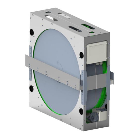
Page 6: Installation
3. INSTALLATION 3.1 Assembly and installation Following illustrations and instructions presents the correct assembling of the motors and controller with the casing of the rotary heat exchanger. Motors are designated to be firmly attached to casing of the exchanger. Pulleys are selected to match the expected speed, efficiencies and performance of the motors. -
Page 7: Connection And Wiring
Figure 6 Stepper Motor 4Nm and 8Nm assembly schematic 3.2 Connection and wiring To perform the correct setup, please refer to the following diagrams representing possible ways of motor connection. Installation and connection can be done by qualified personnel only. Failure in performing in any of this operations may result in risk of fatal injury, electric shock, incorrect mounting or product damage. - Page 8 Figure 7 Stepper motor with male type terminal Figure 8 Connection cable with dedicated terminal Due to length of the motor cables, extension cables connecting motor with the controller are supplied additionally. Extension cable is equipped with 4 pole connectors sleeves fitting terminal of the motors (Figure 11). Lengths of the cables differs depending on the size of the Rotary Heat Exchanger.
- Page 9 To make the wiring process easier it is possible to remove the cover completely by detaching it from the controller. It will provide an easy access to the wiring slots. Hinged brackets allow to detach the doors by light pull (Figure 11).
-
Page 10: Main Voltage And Stepper Motor Wiring
Description Test button 4-pole DIP switch 3 x 7 -segment display – depending on version RJ12 Modbus connector (2 x RJ12) A/D control and signal terminals, depending on version Supply terminals (L, N, PE) Connection terminals for stepper motor (U, V, W, PE) Table 4 Controller slots description 3.2.1 Main voltage and stepper motor wiring The power supply of the controller is 230V AC;... - Page 11 Figure 16 Stepper motor connection Figure 17 Controller schematic...
-
Page 12: Cable Requirements
3.2.2 Cable requirements Before performing the installation, make sure that your setup fulfills the following list of requirements: All cables and leads must comply with the local and national regulations. Cable dimensions for PG9 connectors should be within the range of 3-8mm ... -
Page 13: Led Indicator
Note – motor size and speed settings of the device delivered with the VTS AHU are prepared by the manufacturer for optimal operation and should not be changed. DIP1 DIP2 Stepper motor = 2Nm Stepper motor = 4Nm Stepper motor = 8Nm Table 6 Stepper motor size setting DIP3 DIP4... -
Page 14: Display
3.3.4 Display Display is visible with open and closed cover. The display shows current status for drive, stepper motor and rotor. Code Description Current stepper motor speed is displayed when the stepper motor is running and no rotor or pulley diameter has been entered via respective corresponding Modbus registers. -
Page 15: Modbus And 0-10V Control
Fault code Alarm overview Alarm priority Alarm from rotor guard ”C” Excessive supply voltage ”C” Insufficient supply voltage ”C” Power to the motor increased at a critical level, e.g. short- circuiting ”C” cable, connector or motor Excessive temperature inside OJ-DRHX (>95°C) ”NC”... - Page 16 Figure 21 Spring terminal Modbus connector After 10 seconds without receiving a valid Modbus request with the default parameters, the controller will try to detect a Modbus request with the alternative parameters (see Table 15 to see which registers are responsible for alternative communication parameters).
- Page 17 Adress Function Range Active state Motor ON/OFF 0 - 1 1 = ON Reset Alarms 0 - 1 1 = Reset Rotation direction 0 - 1 1 = CounterClockWise Control mode 0 - 1 0 = Modbus, 1 = 0-10V Use altern.
- Page 18 Adress Function Range Resolution Unit DHX Type 0 - 14 AOC SW version 0 - ? 0.01 PrcOut 0 - 10000 0.01 Intern Temp -5000 - 15000 0.01 ºC Motor Speed Out 0 - 40000 0.01 V In 0 - 300 I Out (RMS) 0 - 10000 Power In...
- Page 19 Adress Function Range Resolution Unit Setpoint / PrcSet 0 - 10000 0.01 Min. Motor Speed 100 - Max. 0.01 Max. Motor Speed Min. - 40000 0.01 Start I Out (Boost) 0 - ? mA (RMS) Start Time (Boost) 0 - ? Sec.
-
Page 20: 0-10V Control
Disabled Start/stop AlarmReset Rotation direction DigIn2 config Test function Ext. rotor guard signal Enable ext. rotor guard DigOut config Disabled Table 15 Available Holding Registers 3.4.2 0-10V control The Rotary Wheel driver is factory-configured for 0-10 V control, which is automatically deactivated when the signal is received via the Modbus protocol, so there is no need for additional configuration when choosing analog control.
Need help?
Do you have a question about the 7-1-0005-0082 and is the answer not in the manual?
Questions and answers