Advertisement
Quick Links
Advertisement

Related Manuals for Teletrac TM470J

Summary of Contents for Teletrac TM470J
- Page 1 Cassens Transport Company Installation Specification Guide Rev 1.1 11/14/2012...
-
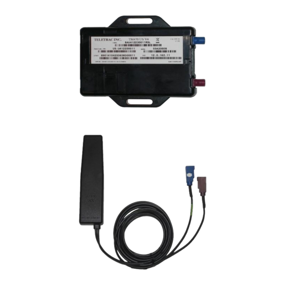
Page 2: Equipment Overview
Equipment Overview Cassens will be utilizing the following equipment package: • TM470J with diagnostics • CTO7 • PTO • HOS (FIL) • Standard wedge antenna All installations must be completed as set forth in this installation specification guide. Any deviation requires approval... -
Page 3: General Installation Requirements
• All cabling must be neatly routed and run, using zip-ties to secure the wiring. • All connections made in the vehicle and all connections on the TM470J must be tamper-sealed using the provided Torque Seal. • The TM470J must be securely mounted , with screws being the preference, but wire-ties being an acceptable alternative, if necessary. - Page 4 Using a Relay to Invert Polarity for PTO Negative Input for Positive PTO Relay Pin Description Ground Not Used Ground PTO (Positive output) Prism (Gray Wire TM2 & TM450, Orange on TM2J) Using the above table, wire the relay in-line, ensuring that all connections are soldered or butt-connected and taped.
- Page 5 TM470J Installation Schematic...
- Page 6 TM470J Cabling Pinout Pin # Function Color MicroPlug Diag RX Input Positive Orange Ground (GND) Black Input Negative Gray Relay driver output (RELAY2) Blue Relay driver output (RELAY1) –FIL- Yellow SAE J1708 bus A signal (J1708A) Yellow (twisted with Blue)
- Page 7 CTO7 Installation Requirements This is only an overview of the CTO7 installation procedure. Please refer to the “CTO7 Kit Instructions” document for a greater level of detail. The CTO7 full kit is shown at top right. The assembled standard mounting bracket is shown at bottom right.
- Page 8 CTO7 Installation Requirements, con’t CTO7 Testing: Prior to calling for verification, please ensure that the following testing procedures have been completed on the CTO7: • Log into HOS using “test” as the username and “1234” as the password. Ensure that HOS field at bottom of screen changes from off duty to on duty.
- Page 9 Sterling LT Series...
- Page 10 Sterling LT Series- CTO and FIL Location The CTO7 is installed on the blank panel of the center dash, as shown at top right. The FIL is installed in the smaller blank panel below the CTO7, to the left of the bank of switches.
- Page 11 PTO Connection: While there is a PTO switch on the dash, it does not provide an adequate output for the TM470J. The best source for PTO is from the passenger’s side relay panel. Carefully remove the panel and connect to the positive output of relay #13, which is for the transmission.
- Page 12 Device Location: The TM470J is mounted directly behind the keyswitch panel to the HVAC vent using two screws, as shown at bottom right.
- Page 13 Mack CH Series...
- Page 14 Mack CH Series- CTO and FIL Location The CTO7 is installed on the blank panel of the center dash, as shown at top right, above the CB radio power connection point. The FIL is installed in the same panel, to the left of the CTO7, centered between and slightly to the right of the air switches.
- Page 15 Once the correct signal wire is determined, it will be connected to the grey wire of the TM470J wiring harness. Diagnostic Connection: The 9-pin Deutsch plug is located on the bottom of the dash, facing downwards, directly below the ignition switch or on the lower driver’s side...
- Page 16 Device Location: The TM470J is mounted with two zipties to the metal side panel behind the lightswitch panel, as shown at bottom right.
- Page 17 Volvo ISX Series...
- Page 18 Volvo ISX Series- CTO and FIL Location The CTO7 is installed on the blank panel, just below the passenger’s side cupholder. Please ensure that the CTO7 is installed just low enough that it can be tilted forwards for fusebox access. The FIL is installed into one of the blank knock-outs, just above the radio and to the left of the CTO7.
- Page 19 TM470J wiring harness. Diagnostic Connection: The 9-pin Deutsch plug is located on the bottom of the dash, facing downwards, adjacent to the driver’s kickpanel.
- Page 20 Device Location: The TM470J is mounted to the HVAC vent behind the headlight panel with two 12” zipties, as shown at bottom right.
Need help?
Do you have a question about the TM470J and is the answer not in the manual?
Questions and answers