
Related Manuals for FM Systems ATU-2

Summary of Contents for FM Systems ATU-2
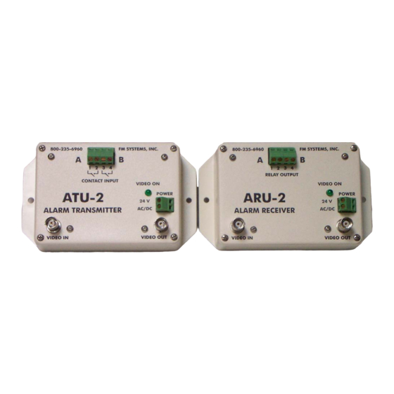
- Page 1 ATU-2 \ ARU-2 ALARM TRANSMITTER \ RECEIVER UNIT INSTRUCTION BOOK IB6362-01 10-1-2002...
- Page 2 TABLE OF CONTENTS DESCRIPTION MOUNTING INSTRUCTIONS HOW TO CABLE THE ATU-2 HOW TO CABLE THE ARU-2 POWER SUPPLY INSTALLATION SET-UP OF THE ATU-2 AND ARU-2 OPERATION CARE AND MAINTENANCE APPLICATIONS (WHERE TO USE THE SYSTEM) ATU-2.ISB...
- Page 3 One channel may be used as a system alarm that will operate upon loss of power to either terminal or loss of transmission path (coax cable cut). In the event of power failure to the ATU-2 or ARU-2 the video thru-put is not interrupted.
- Page 4 (24VAC included). Connect the 24 VAC power transformer to the Green terminal block marked 24V AC/DC. The ATU-2 can be powered by power sources as low as 9 volts AC or DC. However the ARU-2 must be operated with 24 Volts AC or DC.
- Page 5 OPERATION When the units have been installed and are operating you will see that when a contact on the ATU-2 is closed and relay in the ARU-2 closes. Through the video\data path the alarm sense is relayed to the alarm panel or other equipment directly. If there is a power failure the video path is not obstructed by the ATU-2.
Need help?
Do you have a question about the ATU-2 and is the answer not in the manual?
Questions and answers