Table of Contents
Advertisement
Quick Links
Geo-localization and Mosaicing System
Document Information
Title
Subtitle
Document Number
www.senteksystems.com
GEMS
Hardware Integration Manual
GEMS Precision Agriculture Multispectral Payload
Hardware Integration Manual
Rev 2.0- initial release
Page 1 of 25
GEMS- Hardware Integration Manual
8/19/2014
Advertisement
Table of Contents

Summary of Contents for Sentek Sentek
- Page 1 GEMS- Hardware Integration Manual Geo-localization and Mosaicing System GEMS Hardware Integration Manual Document Information Title GEMS Precision Agriculture Multispectral Payload Subtitle Hardware Integration Manual Document Number Rev 2.0- initial release Page 1 of 25 8/19/2014 www.senteksystems.com...
-
Page 2: Table Of Contents
GEMS- Hardware Integration Manual Contents Preface ................................3 Warranty ............................... 3 Technical Support ............................3 Hardware Description ........................... 4 1.1. Overview ............................4 1.2. Architecture ............................5 1.3. Performance Specifications ......................6 1.4. Connecting power ..........................7 1.5. Storage Media ........................... 7 1.6. -
Page 3: Preface
All shipping, insurance, duties and other incidental costs incurred to return the product to Sentek are at the expense of the owner of the product. Sentek will pay the cost of insured shipping only, FOB St. Louis Park MN USA when returning the product after completion of Warranty Service. All other expenses, duties, taxes and other incidental costs are at the expense of the owner. -
Page 4: Hardware Description
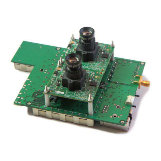
GEMS- Hardware Integration Manual 1. Hardware Description 1.1. Overview GEMS is a precision agriculture multispectral sensor payload for remote sensing on small UAVs. It is designed to be a completely standalone hardware subsystem. The standalone design allows for ease of integration on any size and type of platform (fixed wing, rotary, or RC). -
Page 5: Architecture
GEMS- Hardware Integration Manual 1.2. Architecture The payload is fully integrated with dual global shutter 1.3MP camera modules (RGB & NIR) that are precisely time synchronized to take imagery simultaneously. The camera data is tightly coupled with onboard inertial navigation sensors and a GPS subsystem. The tight integration of the cameras and the navigation provides precisely time synchronized metadata (i.e. -
Page 6: Performance Specifications
GEMS- Hardware Integration Manual 1.3. Performance Specifications Parameter Description Wavelengths Red centered at 615nm bandwidth FWHM = 114nm, Green centered 553nm FWHM = 101nm, Blue centered 450nm FWHM = 101nm, NIR centered at 810nm FWHM = 135nm (Custom filters available upon request) Linear Acceleration +/- 4g Heading Accuracy**... -
Page 7: Connecting Power
3mm pitch. The contacts are fully isolated with a locking mechanism. The Micro-Fit 3.0 is rated up to 5.0 Amperes with a 600V AC rating. Sentek recommends to connect the GEMS payload to its own power source to maintain the payload is a non-mission critical system. -
Page 8: Interface Cable
GEMS- Hardware Integration Manual 1.6. Interface Cable The interface cable plugs into the micro Type A connector on the GEMS Payload board and the other end plugs in the external storage media jump drive included with the GEMS system. Figure 6 Interface Cable 1.7. -
Page 9: Hdmi
The recommended active GPS antenna should be used and installed according to this user integration manual to ensure optimal GPS performance. If a different GPS antenna is used Sentek cannot guarantee accurate reporting of GPS geo-location information. The minimum antenna specifications required is an antenna with omni-directional radiation pattern with a minimum gain of 28dBi. - Page 10 GEMS- Hardware Integration Manual a material it may detune the antenna from 50 Ohms and create degradation to GPS signal or increased dropout. Any additional antennas on the platform should be spaced as far away from the GPS antenna to minimize signal interference. All metal or conductive objects near the GPS antenna will impact performance and should be placed as far away as possible or under the ground plane.
-
Page 11: Gems Payload Installation
Sentek strongly encourages all installation guidelines outlined below to be followed. As a part of the initial purchase of the system Sentek offers a free service that the UAV integrator sends a completed flight dataset to Sentek and our team of engineers provide plots of the platform effects on the payload inertial sensor data. - Page 12 GEMS- Hardware Integration Manual Foam EMI Shields on payload prevent external sources from interfering with our sensors but also act as large heat sinks to our internal processor. We also fly with Foam DO NOT REMOVE! inserted between payload and motors to (Warranty is void if removed) dampen vibrations Figure 8 Example of payload in fuselage illustrating cameras pointing straight down towards ground.
- Page 13 GEMS- Hardware Integration Manual 4 Mounting holes for USB storage media (can be securing payload to utilized in either microUSB plugin) platform Power connector GPS Antenna SMA Connector Figure 10 Connections needed for flying payload and mounting holes for securing payload to platform www.senteksystems.com Page 13 of 25 8/19/2014...
- Page 14 GEMS- Hardware Integration Manual Examples of Good and Poor Payload/Platform Integration: Figure 11 Example of acceptable level of noise from vibrations on accelerometer data X-axis (red), Y-axis (green), Z-axis (blue) Figure 12 Example of Platform with unacceptable level of noise of accelerometer data X-axis (red), Y-axis (green), Z-axis (blue) Page 14 of 25 8/19/2014...
- Page 15 GEMS- Hardware Integration Manual Figure 13 Example of acceptable magnetometer data X-axis (red), Y-axis (green), Z-axis (blue) Figure 14 Example of unacceptable magnetometer data X-axis (red), Y-axis (green), Z-axis (blue) Page 15 of 25 8/19/2014 www.senteksystems.com...
-
Page 16: Led Indicators
GEMS- Hardware Integration Manual 4. LED Indicators The GEMS payload has 3 green LEDs, 1 red LED, and 1 blue LED that indicate to the user the operational state of the device. All states are indicated through the GPIO LED indication cable as well for ease of access on fixed wing platforms when the payload is embedded in a fuselage. -
Page 17: Blue Led
GEMS- Hardware Integration Manual the payload without effecting data. All 3 LEDS should be solid green after completion of a normal flight. Fight can begin after the first flashing green LED turns solid. The user can unmount the jump drive and turn off power to the payload once 3 solid green LEDs are visible. -
Page 18: Safety
GEMS- Hardware Integration Manual 6. Safety Safety precautions should be employed when handling scientific equipment. GEMS has integrated standard practice safety measures to reduce the exposure of electrostatic discharge. RF Shields have been integrated over the PCB to reduce electromagnetic interference with the device and from the device to other devices as well as to mitigate ESD from the system integrators human exposure to the PCB. -
Page 19: Appendix A: Abbreviations
GEMS- Hardware Integration Manual Appendix A: Abbreviations Abbreviation Definition GEMS Geo-localization Mosaicing System Global Positioning Satellites Carrier to Noise Ratio Signal to Noise Ratio Decibels Universal Serial Bus HDMI High Definition Multimedia Interface UART Universal Asynchronous Receiver/Transmitter GPIO General Purpose Input Output Electromagnetic Interference Electromagnetic Compatibility Electromagnetic Discharge... -
Page 20: Appendix B: Calibration
If the GEMS sensor is involved in a serious crash the GEMS payload may be damaged and sensor calibration values may be altered thereby impacting sensor performance. Sentek Systems offers a GEMS repair and calibration service to ensure optimized performance of the GEMS payload. Support engineers are available to determine if this procedure needs to be performed. -
Page 21: Appendix C: Flight Planning Guidelines For Gems
GEMS- Hardware Integration Manual Appendix C: Flight Planning Guidelines for GEMS Introduction GEMS is a self-contained, multi-spectral camera with a built-in, tightly integrated navigation system. The cameras and optics are selected and calibrated to measure relative NDVI (Normalized Difference Vegetation Index) from the air. The system handles the alignment of spectral bands, geo-registration of the imagery, image processing and analysis to render vivid NDVI imagery in false-color, and stitching collected imagery into geo-referenced, ortho-rectified RGB, NIR, and NDVI moasics. - Page 22 GEMS- Hardware Integration Manual Figure 16 recommended flight pattern when covering 2D areas. Flight Profile and Row Spacing The height at which you fly your vehicle is an important parameter which has a direct effect on the ground resolution of the collected imagery (your GSD ) and the time it takes to cover any given area (your coverage rate).
- Page 23 GEMS- Hardware Integration Manual In addition to affecting GSD, the height and speed of your vehicle affects the amount of motion blur (or image smear) in the collected imagery and the amount of image-to-image overlap, which in turn affects the reliability and quality of automatic image stitching. Figure 3 shows which combinations of speed and height result in good, crisp imagery with sufficient image-to-image overlap to enable automatic image stit hi g.
- Page 24 GEMS- Hardware Integration Manual Figure 18 Recommended flight profiles Figure 19 Recommended row spacing versus height Page 24 of 25 8/19/2014 www.senteksystems.com...
- Page 25 GEMS- Hardware Integration Manual Parameters for Flight Planning Software If you use additional software for flight planning, you may need to provide it with some information about your imaging system so it can set an appropriate flight plan. When using tools such as these, set your overlap target to an appropriate value for your subject matter (if you are unsure, start with 70%).
Need help?
Do you have a question about the Sentek and is the answer not in the manual?
Questions and answers