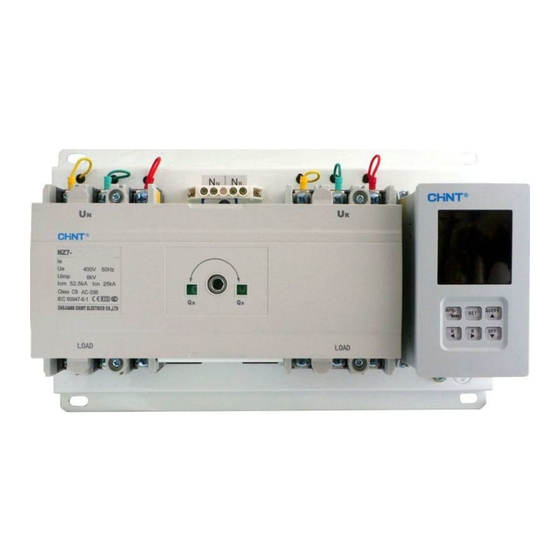
Summary of Contents for CHINT NZ7 Series
- Page 1 N Z 7 S e r i e s A u t o m a t i c T r a n s f e r S w i t c h i n g E q u i p m e n t I n s t a l l a t i o n m a n u a l...
- Page 2 This equipment should only be mounted by professionals. The manufacturer shall not be held responsible for any failure to comply with the instruction given in this manual. The expression right of the instruction is owned by CHINT. The device should only be installed and serviced by professionals.
-
Page 3: Manual Test
Preparations Test 1. Manual test 2. Power test QN: ON QR: ON Manual test Preparations Manual mode Failure alarm Setting mode Stop mode Auto mode Automatic Transfer, Automatic Transfer, Automatic Transfer, operating transfer delay time return transfer delay time Alternative position Power test Operational details of the reference P8 ~ P15... - Page 4 Storage Pollution degree 3 Storage...
- Page 5 The necessary tools Hex key Screw-driver 3N.m 6N.m 8N.m 16N.m 18N.m The necessary tools Standard accessories Optional...
-
Page 6: Installation
Installation Connecting bus-bar type Normal power bus-bar Alternative power bus-bar Line voltage signal sampling Power bus-bar Load bus-bar Vertical installation& horizontal installation Installation Wiring N pole U N pole Wiring terminal of zero line Wiring terminal of zero line Wiring, the voltage signal sampling line in order as shown 3 pole Main circuit Line voltage signal sampling... - Page 7 Installation Wiring diagram of external terminals of the controller Indication of U status Indication of U status Output is AC230V/0.5A Auxiliary power Stop signal DC24V/0.5A Start control of generator Note: the hidden line is the internal wiring of the controller. Installation Controller installed in the cabinet split on the panel CLACK!
-
Page 8: Display And Operation Interface
Installation Display and operation interface Installation Display and operation interface 1. Indication of automatic working mode; 15. Button for compulsorily turn off the normal power 2. Indication of manual working mode; Under the manual control mode, if this button is pressed, it can 3. - Page 9 Installation Operation Description on Parameter Setting Installation The working processes of Type A controller Grid – Grid Grid – Grid Grid-Power Generation self-throw and self-reset operation mutual alternative operation self-throw and self-reset operation is normal is normal is normal fails fails fails T1 can be adjusted from 0s to 180s...
-
Page 10: Wire Connection
Installation Application Terminals 401 and 402 can only connect to passive signal; otherwise, the controller will be burnt! Passive signals may be inputted through relay. Product after receiving the stop signal off, 403 and 404 will be connected. After removing stop signals, this product will restore to normal working status by pressing any key of the controller. - Page 11 Installation Phase barrier NZ7-63 phase barrier assembled by the factory Installation Outline dimension & Installation dimension Outline dimension Installation dimension Wiring terminal of zero line (Only three pole products) Outline dimension...
-
Page 12: Controller Module
Installation Installation dimension Installation Controller Module nstallation dimension of the controller when it is installed by split type...

Need help?
Do you have a question about the NZ7 Series and is the answer not in the manual?
Questions and answers
Добрый день! Подскажите пожалуйста , куда подключить контакты 501 , 502,503 на микроконтроллере АВР CHINT NZ7 к генератору 100 кВт CTG для его запуска и останова двигателя
To connect contacts 501, 502, and 503 on the CHINT NZ7 Series microcontroller to a 100 kW CTG generator for starting and stopping the engine:
- Contact 501: Connect this terminal to the generator's start input. It sends the start signal when generator mode is active.
- Contact 502: Connect this as the common terminal (COM) in the control circuit.
- Contact 503: Connect this terminal to the generator's stop input. It sends the stop signal to shut down the generator.
Ensure these connections match the generator’s control signal requirements and follow safety procedures during installation.
This answer is automatically generated