
Subscribe to Our Youtube Channel
Related Manuals for Technibel MAFX93-123

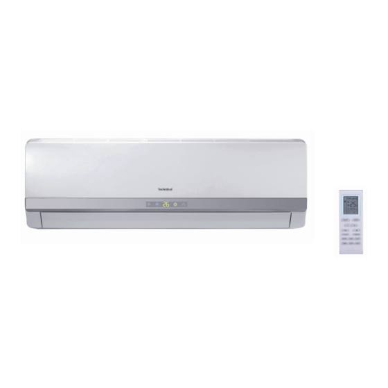
Summary of Contents for Technibel MAFX93-123
- Page 1 Condizionatore d’aria split - Split air conditioner • Climatiseur split Split-klimagerät - Acondicionador de aire split MAFX/GRFX93-123 DC INVERTER SERVICE MANUAL...
- Page 2 Model MAFX93 MAFX123 Indoor unit model MAFX93R5I MAFX123R5I Product Code Rated Voltage 220-240 220-240 V~ Rated Frequency Phases Power Supply Mode Indoor Indoor Cross-sectional Area of Power Cable Conductor 1,50 1,50 Recommended Power Cable(Core) Min/Max. Voltage 198/264 198/264 Cooling Capacity 2700 3500 Cooling Capacity...
- Page 3 Model MAFX93 MAFX123 1260/1050/900/690 1290/1070/900/690 Cooling Speed r/min 1320/1200/1000/910 1280/1050/980/920 Heating Speed r/min Indoor Unit Fan Motor Power Output Indoor Unit Fan Motor RLA 0,10 0,10 Indoor Unit Fan Motor Capacitor µF Heater Power Input Evaporator Form Aluminum Fin-copper Tube Aluminum Fin-copper Tube Evaporator Pipe Diameter φ7...
- Page 4 Model MAFX93 MAFX123 Outdoor Unit Fan Type Axial-flow Axial-flow Outdoor Unit Fan Diameter 15 3/4 15 3/4 Outdoor Unit Fan Diameter inch Outdoor Unit Fan Motor Speed 900/660 900/660 Outdoor Unit Fan Motor Power Output Outdoor Unit Fan Motor RLA 0,15 0,15 Outdoor Unit Fan Motor Capacitor...
- Page 6 Cooling Heating Condition Condition Indoor:DB 20 Indoor:DB 27 WB19 Indoor air flow:Turbo Indoor air flow: Turbo Pipe length:5m Pipe length:5m Voltage:230V Voltage:230V Compressor Speed(rps) Compressor Speed(rps) n i l Condition Condition Indoor:DB20℃ Indoor:DB27℃ WB19℃ Indoor air flow: Turbo Indoor air flow: Turbo Pipe length:5m Pipe length:5m...
- Page 7 Indoor side noise when blowing Outdoor side noise when Compressor speed changed Supper High High Middle Indoor fan motor rotating speed Compressor Speed(rps)
- Page 8 Φ55 Φ55...
- Page 9 4-Way valve HEAT EXCHANGER (EVAPORATOR) Accumlator Compressor HEAT EXCHANGER (EVAPORATOR) Strainer Strainer Electron expansion valve COOLING HEATING...
- Page 10 POWER ROOM DISPLAY TUBE TEM.SENSOR TEM.SENSOR YEGN θ θ W1 BU N(1) DISP-1 DISP-2 W2 BK ROOM TUBE COM-OUT W3 BN YEGN AC-L L-OUT W4 YEGN JUMP EVAPORATOR SWING-UD HEALTH-L HEALTH-N COOL PLASMA GENERATOR YEGN SWING MOTOR(U.D) FAN MOTOR...
- Page 11 TUBE OUTROOM EXHAUST TEM. S ENSOR TEM. S ENSOR TEM. S ENSOR RT1 RT2 RT3 YEGN θ θ θ LX1-2 LX1-1 AC-L2 AC-L3 N(1) AC-N1 COM-OUT AC-N AC-N2 AC-L YEGN OVC-COMP AC-L1 AC-L OFAN U V W MID.ISOLATION SHEET ELECTRIC BOX L2 L2 NOTE: YEGN...
-
Page 12: Top View
TOP VIEW Solid-state relay Port of neutral wire Auto button Feedback of indoor fan Live wire of health function Port of indoor fan Port of motor for vertical swing Port of motor for horizontal swing Protective tube Buzzer Port of indoor ambient temp sensor Port of indoor pipe temp sensor... - Page 13 compressor fan neilsbed inductance pin1 four-way valve electric heater inductance pin2 chassis electric heater 10-core communication cable compressor temp. sensor overload protection electric expansion valve...
-
Page 14: Antifreezing Protection
1. Temperature Parameters Indoor preset temperature (T preset Indoor ambient temperature (T amb. 2. Basic Functions Once energized, in no case should the compressor be restarted within less than 3 minutes. In the situation that memory function is available, for the first energization, if the compressor is at stop before de-energization, the compressor will be started without a 3-minute lag;... - Page 18 O(0 ) heating angle cooling angle O(0 )
- Page 22 Space to the ceiling Above Space to the wall Above Space to the wall Above Above Air outlet side Space to the floor The dimensions of the space necessary for proper installation of the unit includ e the minimum permissible distances to adjacent parts . Space to the obstruction Air inlet side Space to the wall...
- Page 23 Wall Above 150 from the ceiling Wall Wall Above Above 150 from 150 from the wall the wall Φ55 Φ55 Left Right Indoor Outdoor Wall pipe Seal pad outlet pipe of indoor unit outlet pipe of drain hose indoor unit rubber belt outlet pipe of drain hose...
- Page 24 External connection Gas side pipe electric wire Liquid side piping Gas side piping Tailing 2 Liquid side insulation Tailing 1 Piping insulation Finally wrap it Fig.3 Water drainage pipe with tape Left Right Left rear Fig.4 Right rear Fixing hook Mounting plate Mounting...
-
Page 25: Bottom Frame
Manifold Valve Multimeter Manometer -76cmHg Hi handle Lo Handle Charging hose Low pressure valve Vacuum pump Fig.6 Drain-water hole Bottom frame Drain connecter Hose (available commercially, inner dia. 16mm) - Page 26 Fig.a Fig.b Air filter Healthy filter Fig.c...
- Page 27 Measure insulation resistance The breaker trips at once when it to ground to see if there is any is set to “ON”. leakage. Trip of breaker or blow of fuse The circuit or the part of the air conditioner has malfunction. They heat and break the insula- tion and lead to short circuit or The breaker trips in few minutes...
- Page 28 Improper set of temperature Adjust set temperature If cooling (heating) load is Check the forecasted load of cooling (heating) proper Check and fill the leakage, then The refrigerant has leakage or is vacuumize it and supplement the re- insufficient frigerant as required Leakage between the high pres- Replace the compressor sure and the low pressure in-...
- Page 29 The indoor fan motor is burned or breaks or has the heat protector Replace the fan motor or the defective part. malfunction. The built-in heat protector of the Replace the fan motor The fan does not motor breaks frequently because the run when it is set motor is abnormal.
- Page 30 The torque of the swing motor is not enough First, check whether the connection is Wrong connection The swing fan wrong. If no, replace the parts does not run. The controller is damaged(IC2003 is damaged, the swing relay can not close, etc) C o n t r o l l e r m a l f u n c t i o n ( I C 2 0 0 3 Change controller...
- Page 31 Display Method of Outdoor Display Method of Indoor Unit Unit Indicator has 3 kinds of Indicator Display (during display status and during Malfunction blinking, ON 0.5s and OFF Dual-8 A/C status Possible Causes blinking, ON 0.5s and OFF Name 0.5s) Code 0.5s Display...
- Page 32 Display Method of Outdoor Display Method of Indoor Unit Unit Indicator has 3 kinds of Indicator Display (during display status and during Malfunction blinking, ON 0.5s and OFF Dual-8 A/C status Possible Causes blinking, ON 0.5s and OFF Name 0.5s) Code 0.5s Display...
- Page 33 Display Method of Outdoor Display Method of Indoor Unit Unit Indicator has 3 kinds of Indicator Display (during display status and during Malfunction blinking, ON 0.5s and OFF Dual-8 A/C status Possible Causes blinking, ON 0.5s and OFF Name 0.5s) Code 0.5s Display...
- Page 34 Display Method of Outdoor Display Method of Indoor Unit Unit Indicator has 3 kinds of Indicator Display (during display status and during Malfunction blinking, ON 0.5s and OFF Dual-8 A/C status Possible Causes blinking, ON 0.5s and OFF Name 0.5s) Code 0.5s Display...
- Page 35 Display Method of Outdoor Display Method of Indoor Unit Unit Indicator has 3 kinds of Indicator Display (during display status and during Malfunction blinking, ON 0.5s and OFF Dual-8 A/C status Possible Causes blinking, ON 0.5s and OFF Name 0.5s) Code 0.5s Display...
- Page 36 Display Method of Outdoor Display Method of Indoor Unit Unit Indicator has 3 kinds of Indicator Display (during display status and during Malfunction blinking, ON 0.5s and OFF Dual-8 A/C status Possible Causes blinking, ON 0.5s and OFF Name 0.5s) Code 0.5s Display...
- Page 37 Display Method of Indoor Unit Display Method of Outdoor Unit Indicator Display (during Indicator has 3 kinds of display blinking, ON 0.5s and OFF status and during blinking, ON Dual-8 Malfunction A/C status Possible Causes 0.5s) 0.5s and OFF 0.5s Code Name Operation...
- Page 38 Turn on the unit and wait 1 minute Use DC voltmeter to measure the voltage on the two ends of electrolytic capacitor Fault with the voltage Replace the control testing circuit on Voltage higher than 200V? panel AP1 control panel AP1 Measure the AC voltage between terminal L and N on wiring board XT(power supply)
- Page 39 Energize and switch on Use AC voltmeter If the voltage Check the supply to measure the IPM protection between terminal L voltage and voltage between occurs after the and N on wiring machine has run for terminal L and N restore it to board XT is within a period of time?
- Page 40 Overheat and high temperature protection Normal protection, please operate it after the outdoor ambient temp- Is outdoor ambient temperature higher than 53? erature is normalized. 20 minutes after the complete unit is powered off. Improve the heat Is heat dissipation of the indoor unit dissipation environ- and outdoor unit abnormal? ment of the unit...
- Page 41 Power on the unit Restart it up after Is stop time of the compressor 3 minutes longer than 3 minutes? Does startup fail? Connect the wires as Are the wires for the compressor connected per the connection correctly? Is connection sequence right? diagram Replace the control panel AP1 If the fault is eliminated?
- Page 42 Out of step occurs in Out of step occurs once the operation unit is powered on. Check if the fan terminal Is stop time of the Replace the fan Is the outdoor fan working OFAN is connected correctly compressor longer than capacitor C1 normally? 3 minutes?
- Page 43 20 minutes after the complete unit is powered off Is the terminal FA for the Connect the electronic expansion valve wires correctly connected correctly? Resistances between the first four pins close to the terminal hole and the fifth pin are almost the same, less than 100 ohm.
- Page 44 Start Check wiring of the reactor (L) of the outdoor unit and the PFC capacitor Replace it as per the Whether there is any wiring diagram and If the fault is eliminated? damage or reconnect the wires short-circuit? Remove the PFC capacitor and measure resistance between the two terminals.
- Page 45 Start Did the equipment operate normally before the failure occurs? Check the wiring of the indoor and outdoor units with reference to the wiring diagram Check wiring inside of the indoor and outdoor Is the connection right? units Correctly connect the corresponding wires for The AP1 voltage Are wires broken?
- Page 47 Start Measure voltage at the Test 10 position as shown in the diagram with a voltmeter Value jumping Measure voltage at the Test 15 position as shown in the diagram with a voltmeter Value jumping Fault with outdoor unit Measure voltage at the Test 11 position as shown in the diagram with a voltmeter...
- Page 54 Steps Procedure 1.Remove big handle Before disassamble. Remove 1 connection screw fixing big handleand then removethe big handle. big handle 2. Remove top cover top cover Remove 3 connection screws among top cover plate, front panel and right sideplate. Then remove top cover plate.
- Page 55 3.Remove grille and front panel Remove connection screws between the front grille and the front panel. Then remove the front grille. Remove connection screws connecting the front panel with the chassis and the motor support, and then remove the front panel. Grille Panel 4.Remove axial flow blade...
- Page 56 6.Remove electric box assy Electric box assy Remove the 2 screws fixing the cover of elec- tric box. Lift to remove the cover. Loosen the wire and disconnect the terminal. Lift to re- move the electric box assy. 7.Remove 4-way valve assy Unscrew the fastening nut of the 4-way Valve 4-way Valve Assy Assy coil and remove the coil.
- Page 57 9.Remove motor and motor support Motor support Remove the 4 tapping screws fixing the motor. Pull out the lead-out wire and remove the Motor motor. Remove the 2 tapping screws fixing the motor support. Lift motor support to re- move it. 10.Remove clapboard sub-assy Clapboard Sub-Assy Loosen the screws of the Clapboard Sub-Assy .
- Page 58 11.Remove Compressor Remove the 2 screws fixing the gas valve. Unsolder the welding spot connecting gas valve and air return pipe and remove the gas valve. (Note: it is necessary to warp the gas valve when unsoldering the welding spot.) Remove the 2 Liquid valve screws fixing liquid valve.
- Page 60 F-GAS REGULATION (EC) no. 842/2006 Non disperdere R410A nell'atmosfera: R410A è un gas fluorinato a effetto serra, coperto dal protocollo di Kyoto, con potenziale di riscaldamento globale (GWP) = 1975. Do not vent R410A into atmosphere: R410A is a fluorinated greenhouse gas, covered by Kyoto Protocol, with a Global Warming Potential (GWP) = 1975.
Need help?
Do you have a question about the MAFX93-123 and is the answer not in the manual?
Questions and answers