
Summary of Contents for TRUCK PB-XEPI
- Page 1 FIELDBUS TECHNOLOGY ETHERNET- PROFIBUS- INTERFACE PB-XEPI INSTALLATION MANUAL F1144/...
- Page 2 Installation PB-XEPI D301144 0509...
-
Page 3: Table Of Contents
Menu and keyboard commands ..............5 For your safety ....................6 Performance and functioning ...............8 PB-XEPI features ..................8 Scope of delivery ..................8 PB-XEPI Configuration requirements ............8 Ethernet network presettings ................8 Design of the device ..................9 Connections and indicating elements ............10 Mounting ....................10 Start-up guideline ..................11... - Page 4 Content PB-XEPI operation modes PROFIBUS Diagnosis .................20 PROFIBUS network access ................21 Troubleshooting ...................22 Technical data ....................23 Installation PB-XEPI D301144 0509...
-
Page 5: About This "Installation Manual
Menu and keyboard commands The following conventions apply to menu and keyboard commands: Window names, menu items, fields and descriptions of Courier font combo boxes, check boxes, radio buttons and icons. <Key> Press the indicated key. D301144 0509 Installation PB-XEPI... -
Page 6: For Your Safety
In case of high temperature differences, please wait at least three hours before operating the device. – Lock the connected plug (PROFIBUS) using the screw connections intended for this purpose. Installation PB-XEPI D301144 0509... - Page 7 For your safety Disposal The device must be disposed of separately from normal household waste in accordance with the 2002/96/EC (WEEE) Directive. D301144 0509 Installation PB-XEPI...
-
Page 8: Performance And Functioning
Performance and functioning Performance and functioning The Ethernet-PROFIBUS-Interface (PB-XEPI) as a compact gateway enables an easy connection of PROFIBUS networks to the Ethernet. PB-XEPI features – Supports 2 operation modes: integrated of the entire PROFIBUS network with alert via PROFIBUS diagnosis... -
Page 9: Design Of The Device
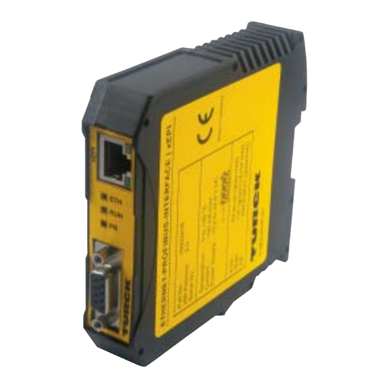
Temperature: 0...+50 °C Current: max. 190 mA Power Supply: 19,2...28,8 VDC + – 24 VDC ETH: Ethernet (GN/RD) RUN: OK (GN) Error (RD) PROFIBUS (GN/RD) Made in Germany D-Mülheim/Ruhr Fig. 1: PB-XEPI (front and side view) D301144 0509 Installation PB-XEPI... -
Page 10: Connections And Indicating Elements
[6] Terminal strip for +24 VDC power supply – A: 24 V (+) – B: 0 V (-) – C: not assigned – D: Earth conductor Mounting – 35 mm DIN rail [8] (not included in the scope of delivery) Installation PB-XEPI D301144 0509... -
Page 11: Start-Up Guideline
(not included in the scope of delivery). Note regarding the application software An application software with the appropriate drivers is required for operating the device. The COM-DTM for usage of the PB-XEPI in FDT frame applications is on the CD. D301144 0509 Installation PB-XEPI... -
Page 12: Assembling And Disassembling The Device
Insert the patch cable plug (RJ45, not included in the scope of delivery) into the Ethernet socket on the device until the plug locks into place. The green LED on the Ethernet socket lights as soon as the device is energized and an Ethernet network is available. Installation PB-XEPI D301144 0509... -
Page 13: Connecting The Power Supply
The terminal strip can be plugged and lifted out using a screwdriver for installation. Switch on the power supply. The LED RUN flashes green until the device's initiation procedure is completed. Afterwards the LED RUN lights green. D301144 0509 Installation PB-XEPI... -
Page 14: Configuring The Device In The Ethernet Network
If you connect the Ethernet with the power supply already connected, the DHCP may fail to be identified. The routine for the DHCP identification only runs during device start-up. Briefly switch off the power supply for a new DHCP identification. Installation PB-XEPI D301144 0509... -
Page 15: Connection In A Network With Manual Ip Assignment
If you set an address already assigned, other devices in the network may be deactivated and communication may be affected. The device has the following manual default IP addresses (default settings at the time of delivery): IP address 169.254.0.1 Subnet Mask 255.255.0.0 Standard gateway 0.0.0.0 D301144 0509 Installation PB-XEPI... -
Page 16: Determining The Network Addresses
Start a Web browser on your PC/notebook (MS Internet Explorer 6 or 7). Enter the IP address http://169.254.0.1 and press <Enter>. The PB-XEPI web site loads. A pop-up window opens. Please read the information carefully and close the window after that. -
Page 17: Checking The Ethernet Connection To The Device
(e.g.: Turck_000915 ) and press <Enter>. – Manual IP configuration: Enter the set IP address (basic setting: 169.254.0.1 and press <Enter>. Information on the PROFIBUS network is displayed in the web browser. D301144 0509 Installation PB-XEPI... -
Page 18: Connecting The Profibus
Fig. 5: Possibilities for interface connection in the PROFIBUS network 1 Connection at end/start of bus with terminating resistor 2 Connection in the middle of the PROFIBUS segment 1 3 Connection in a seperate PROFIBUS segment behind a repeater. Installation PB-XEPI D301144 0509... -
Page 19: Bus Terminating Resistors
The setting of the PROFIBUS parameters is only required, if you use the device as a class 2 PROFIBUS master or in the operation mode PROFIBUS network access. The PROFIBUS parameters are given by the class 1 PROFIBUS master. D301144 0509 Installation PB-XEPI... -
Page 20: Pb-Xepi Operation Modes
(Default is the six-figure serial number of the device). Select View - PROFIBUS diagnosis . Here you can configure the settings of Measurement, Alert Time Server. If you need help, click on the question mark. Fig. 7: PROFIBUS diagnosis settings Installation PB-XEPI D301144 0509... -
Page 21: Profibus Network Access
PROFIBUS network access PROFIBUS network access PROFIBUS network access operation mode enables use of the PB-XEPI for other applications (PROFIBUS Scope from Trebing & Himstedt, TH OPC Server DP from Trebing & Himstedt, FDT frame application with CommDTM PROFIBUS DP- ®... -
Page 22: Troubleshooting
Automatic detection PB-XEPI as active station (PROFIBUS network access): – Check the PROFIBUS parameters for the channel used (see application software, not included in the scope of delivery). Each station has its own station address, which can only be assigned once in the network. -
Page 23: Technical Data
B line data+ (RxD/TxD-P) Pin 4 Pin 5 GND (0 V) Pin 6 Potential (+5 VDC) Pin 7 not assigned Pin 8 A line data– (RxD/TxD-N) Pin 9 not assigned Other Ethernet connection Type RJ45 (10Base-T/100Base-TX) Certificates D301144 0509 Installation PB-XEPI... - Page 24 Technical data Installation PB-XEPI D301144 0509...
- Page 25 D301144 0509 Installation PB-XEPI...
- Page 26 www.turck.com TURCK WORLD-WIDE HEADQUARTERS GERMANY Hans Turck GmbH & Co. KG Witzlebenstraße 7 45472 Mülheim an der Ruhr Phone +49 (0) 208 4952-0 +49 (0) 208 4952-2 64 E-Mail more@turck.com D301144 0509 *D301143ßß0509* Subject to change without notice...
Need help?
Do you have a question about the PB-XEPI and is the answer not in the manual?
Questions and answers