Table of Contents
Advertisement
Quick Links
Chipsmall Limited consists of a professional team with an average of over 10 year of expertise in the distribution
of electronic components. Based in Hongkong, we have already established firm and mutual-benefit business
relationships with customers from,Europe,America and south Asia,supplying obsolete and hard-to-find components
to meet their specific needs.
With the principle of "Quality Parts,Customers Priority,Honest Operation,and Considerate Service",our business
mainly focus on the distribution of electronic components. Line cards we deal with include
Microchip,ALPS,ROHM,Xilinx,Pulse,ON,Everlight and Freescale. Main products comprise
IC,Modules,Potentiometer,IC Socket,Relay,Connector.Our parts cover such applications as commercial,industrial,
and automotives areas.
We are looking forward to setting up business relationship with you and hope to provide you with the best service
and solution. Let us make a better world for our industry!
Contact us
Tel: +86-755-8981 8866 Fax: +86-755-8427 6832
Email & Skype: info@chipsmall.com Web: www.chipsmall.com
Address: A1208, Overseas Decoration Building, #122 Zhenhua RD., Futian, Shenzhen, China
Advertisement
Table of Contents

Related Manuals for Nordic Semiconductor nRF51822-mKIT


Summary of Contents for Nordic Semiconductor nRF51822-mKIT
- Page 1 Chipsmall Limited consists of a professional team with an average of over 10 year of expertise in the distribution of electronic components. Based in Hongkong, we have already established firm and mutual-benefit business relationships with customers from,Europe,America and south Asia,supplying obsolete and hard-to-find components to meet their specific needs.
- Page 2 Kit nRF51822-mKIT User Guide v1.0 Copyright © 2014 Nordic Semiconductor ASA. All rights reserved. Reproduction in whole or in part is prohibited without the prior written permission of the copyright holder.
-
Page 3: Minimum Requirements
nRF51822 mbed Kit User Guide v1.0 Introduction The nRF51822 mbed kit is a stand-alone platform for rapid prototyping of Bluetooth® Smart designs with the nRF51822 SoC. The mbed kit gives access to all GPIO pins through pin headers and incorporates a coin-cell battery holder for portability enabling in-situ evaluation and test. -
Page 4: Kit Content
nRF51822 mbed Kit User Guide v1.0 Kit content The nRF51822 mbed kit consists of hardware and access to software components, documentation, and design files from www.mbed.org or www.nordicsemi.com. nRF51822 mbed kit hardware content 1 x Lithium 3 V battery 1 x nRF51822 mbed kit board (PCA10024) Figure 1 nRF51822 mbed kit hardware content Page 3... -
Page 5: Downloadable Content
nRF51822 mbed Kit User Guide v1.0 Downloadable content The nRF51822 mbed kit includes access to the mbed online toolchain and source code, documentation, hardware schematics, and layout files. To access this information, go to www.mbed.org www.nordicsemi.com. 2.2.1 nRF51822 documentation • nRF51822 mbed Kit User Guide •... -
Page 6: Getting Started
nRF51822 mbed Kit User Guide v1.0 Getting started This section shows you how to get access to the mbed web site, tools, libraries, and documentation. Connect your nRF51822 mbed kit to a computer. 1. Connect your mbed kit to a computer with a USB cable. 2. -
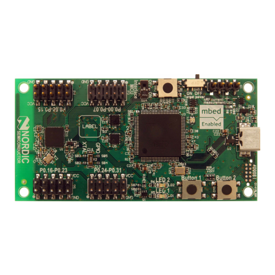
Page 7: Hardware Description
nRF51822 mbed Kit User Guide v1.0 Hardware description The nRF51822 mbed kit board (PCA10024) is a standalone mbed enabled development board. The board is delivered with an unprogrammed nRF51822 chip. Key features The mbed kit board has the following key features: •... - Page 8 nRF51822 mbed Kit User Guide v1.0 Figure 5 mbed kit board bottom nRF51822 reset The Reset button (SW3) is connected to the Interface MCU, therefore the mbed kit board needs to be powered through USB and the Interface MCU switch (SW4) must be switched to ON in order to reset the nRF51822 chip by pressing the reset button.
-
Page 9: Power Supply
nRF51822 mbed Kit User Guide v1.0 Power supply The mbed kit board has several power options as seen in Figure 7 and Figure 8. • USB • External power supply through P1 (1.8 V to 3.6 V) • CR2032 coin cell battery Figure 7 USB and external power supply Coin cell battery holder... - Page 10 nRF51822 mbed Kit User Guide v1.0 The 5 V from the USB is regulated down to 3.3 V through an on-board voltage regulator. The battery and external power supply are not regulated. The power sources are routed through a set of diodes (D1A, D1B, and D1C) where the circuit is supplied from the source with the highest voltage.
- Page 11 nRF51822 mbed Kit User Guide v1.0 Interface MCU disconnect The Interface MCU circuit on the mbed kit board only works when the board is powered through the USB connector. To ensure that the Interface MCU will not hold any of the SWD or UART lines while powered down, the SWD lines will be disconnected automatically when the USB cable is unplugged.
-
Page 12: Gpio Interface
nRF51822 mbed Kit User Guide v1.0 GPIO interface Access to the nRF51822 GPIOs is available at connectors P3, P4, P5, and P6 on the mbed kit board. Figure 11 GPIO pin headers Note: Some pins have default settings. • P0.26 and P0.27 are by default used for the 32 kHz crystal and are not available on the P6 connector. -
Page 13: Buttons And Leds
nRF51822 mbed Kit User Guide v1.0 Buttons and LEDs The two buttons and two LEDs on the mbed kit board are connected to dedicated I/Os on the nRF51822 chip. The connections are shown in Table 1. Part GPIO Short Button 1 P0.16 Button 2 P0.17... -
Page 14: Khz Crystal
nRF51822 mbed Kit User Guide v1.0 32.768 kHz crystal nRF51822 can use an optional 32.768 kHz crystal (X2) for higher accuracy and lower average power consumption. On the mbed kit board, P0.26 and P0.27 are by default used for the 32.768 kHz crystal and are not available as GPIOs on the P6 connector. -
Page 15: Measuring Current
nRF51822 mbed Kit User Guide v1.0 4.10 Measuring current The current drawn by the nRF51822 device can be monitored on the mbed kit board. To measure the current, you must first prepare the board by cutting the shorting of solder bridge SB8. There are two ways of measuring the current consumption: 1. -
Page 16: Troubleshooting
nRF51822 mbed Kit User Guide v1.0 Troubleshooting The Interface MCU serial port is not working. In order to use the USB to UART bridge in Windows, make sure that you have the mbed Windows serial port driver installed and that the Interface MCU switch (SW4) is set to ON. Reset button is not responding. -
Page 17: Liability Disclaimer
Kit User Guide v1.0 Liability disclaimer Nordic Semiconductor ASA reserves the right to make changes without further notice to the product to improve reliability, function or design. Nordic Semiconductor ASA does not assume any liability arising out of the application or use of any product or circuits described herein.
Need help?
Do you have a question about the nRF51822-mKIT and is the answer not in the manual?
Questions and answers