Table of Contents
Advertisement
Quick Links
BL6-U Parallel Integrated Controller Quick Commissioning User Manual
1 BL6-U PARALLEL INTEGRATED CONTROLLER MODEL & SPECIFICATIONS ................................. 1
1.1 M
ODEL DESCRIPTION
1.2 S
................................................................................................................................... 2
PECIFICATIONS
2 BL6-U PARALLEL INTEGRATED CONTROLLER MAIN BOARD TERMINALS .................................. 4
3 PG CARD TERMINALS & ASSEMBLAGE .................................................................................. 8
3.1 PG_V6 ............................................................................................................................................. 8
3.2 PG_V6X ........................................................................................................................................... 9
3.3 SPG_V6 ........................................................................................................................................... 9
3.4 SPG_V6E ....................................................................................................................................... 11
4 PARAMETER NEED TO SET BEFORE INSPECTION RUN .......................................................... 12
5 MOTOR INITIAL ANGLE TUNING (ONLY FOR SYNCHRONOUS MACHINE) ............................... 14
6 ASYNCHRONOUS MOTOR ADJUSTMENT ............................................................................. 19
6.1 M
P
OTOR
ARAMETERS
6.2 E
P
NCODER
ARAMETERS
6.3 PI P
C
ARAMETERS
ONFIRMATION
6.4 E
S
C
LEVATOR
YSTEM
ONFIRMATION
7 INSPECTION RUNNING....................................................................................................... 22
7.1 T
HINGS TO CHECK BEFORE INSPECTION RUNNING
7.2 I
NSPECTION RUNNING
8 HOISTWAY PARAMETER LEARNING .................................................................................... 23
8.1 P
H
ERFORM
OISTWAY
8.2 P
H
ERFORM
OISTWAY
8.3 H
P
OISTWAY
ARAMETER
9 START-UP COMFORT LEVEL ADJUSTMENT ........................................................................... 26
9.1 C
OMFORT LEVEL ADJUSTMENT WITH WEIGHING DEVICE
9.2 S
L
TART WITHOUT
OAD
9.3 E
LEVATOR NORMAL SPEED COMFORT LEVEL ADJUSTMENT
10 LEVELING PRECISION ADJUSTMENT .................................................................................. 29
10.1 B
C
ASIC
ONDITIONS FOR
10.2 L
P
EVELING
ARAMETER
11 INTEGRATED CONTROLLER TERMINAL WIRING DIAGRAM ................................................. 30
APPENDIX I BL6-U PARALLEL INTEGRATED CONTROLLER TEST COMMISSIONING .................. 31
APPENDIX II BL6-U PARALLEL INTEGRATED CONTROLLER OPERATOR MENU ........................ 32
APPENDIX III LEVELING SWITCHES & FLAG INSTALLATION ................................................... 33
APPENDIX IV PARAMETERS ................................................................................................ 34
APPENDIX V ELEVATOR SYSTEM FAULTS.............................................................................. 45
APPENDIX VI DRIVER FAULT ............................................................................................... 48
APPENDIX VII MENU OPERATION PROCESSES WITH DIGITAL TUBES & OPERATION KEYS ...... 53
Contents
............................................................................................................................ 1
C
................................................................................................... 19
ONFIRMATION
C
................................................................................................. 19
ONFIRMATION
........................................................................................................... 20
........................................................................................................ 20
: .................................................................................... 22
......................................................................................................................... 22
P
L
ARAMETER
EARNING WITH
P
L
ARAMETER
EARNING WITH
L
F
D
EARNING
AULT
IAGNOSIS
C
S
........................................................................................ 26
OMPENSATION
ETUP
E
L
......................................................................................... 29
LEVATOR
EVELING
A
................................................................................................... 29
DJUSTMENT
D
O
........................................................ 23
IGITAL
PERATOR
D
T
& O
IGITAL
UBES
PERATION
................................................................................ 24
............................................................................. 26
........................................................................... 28
K
................................... 24
EYS
Advertisement
Table of Contents

Summary of Contents for BLUELIGHT BL6-U
- Page 1 BL6-U Parallel Integrated Controller Quick Commissioning User Manual Contents 1 BL6-U PARALLEL INTEGRATED CONTROLLER MODEL & SPECIFICATIONS ......... 1 1.1 M ..........................1 ODEL DESCRIPTION 1.2 S ........................... 2 PECIFICATIONS 2 BL6-U PARALLEL INTEGRATED CONTROLLER MAIN BOARD TERMINALS ........4 3 PG CARD TERMINALS &...
-
Page 2: Model Description
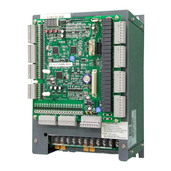
BL6-U Parallel Integrated Controller Quick Commissioning User Manual 1 BL6-U Parallel Integrated Controller Model & Specifications 1.1 Model description Model description of BL6-U Parallel Integrated Controller is shown as figure 1(take 22KW closed type controller as example). Specifications list in chart 1. -
Page 3: Specifications
BL6-U Parallel Integrated Controller Quick Commissioning User Manual 1.2 Specifications Specifications of BL6-U Parallel Integrated Controller in chart 1. 1.1 S HART PECIFICATIONS 4005 4007 4011 4015 4018 4022 4030 4037 4045 BL6-U□40□□-B ODEL 4055 4075 18.5 (KW) AX MOTOR CAPACITY... - Page 4 BL6-U Parallel Integrated Controller Quick Commissioning User Manual 1.1 S (Cont’d) HART PECIFICATIONS TART WITHOUT OMPENSATION BATTERY OPERATION AUTO TUNING OMPENSATION COOLING FAN CONTROL BASE BLOCK TORQUE LIMIT , S C COMMUNICATION CCELERATION DECELERATION TIME URVE AIN CONTROL FUNCTIONS CCELERATION...
- Page 5 BL6-U Parallel Integrated Controller Quick Commissioning User Manual 2 BL6-U Parallel Integrated Controller Main Board Terminals Digital operator Digital tubes & operation keys interface 4x Φ 4.0 Input interface Output interface 204 213 PG card interface Power & CAN Bus Bidirectional interface 2.1 T...
- Page 6 BL6-U Parallel Integrated Controller Quick Commissioning User Manual 2.1 Control Circuit Port definition and Function HART Interface Tech Spec Port Terminal Location Definition Usage Interface Rated On/off Symbol Type Capacity Time Speed X36+ J1-1 Door inter-lock input + (110V-220VAC) AC110V...
- Page 7 BL6-U Parallel Integrated Controller Quick Commissioning User Manual Control Circuit Port definition Function (Cont’d) HART Interface Tech Spec Port Terminal Location Definition Usage Interface Rated On/off Symbol Type Capacity Time Speed Full Collective/Simplex Collective J5-5 Car call input 4/ Car call input 4...
- Page 8 BL6-U Parallel Integrated Controller Quick Commissioning User Manual 2.1 Control Circuit Port definition and Function (Cont’d) HART Interface Tech Spec Port Terminal Location Definition Usage Interface Rated On/off Symbol Type Capacity Time Speed J9-10 SSDZ top terminal input J9-9 SXDZ bottom terminal input...
- Page 9 BL6-U Parallel Integrated Controller Quick Commissioning User Manual 3 PG Card Terminals & Assemblage Note: With the hardware version upgrade, the corresponding pictures may be changed. Reference to prevail in kind. 3.1 PG_V6 PG_V6 interface card is sync/async machine universal pulse encoder speed feedback and frequency dividing output card.
- Page 10 BL6-U Parallel Integrated Controller Quick Commissioning User Manual 3.2 PG_V6X PG_V6X interface card is async machine universal pulse encoder speed feedback and frequency dividing output card. PG_V6X is in supporting use of 12V OC output and push-pull output type pulse encoder.
- Page 11 BL6-U Parallel Integrated Controller Quick Commissioning User Manual machine: A/B, and encoder for sync machine: A/B/R/C/D. Refer to Figure 3.3 below for detail. 3.3 SPG_V6 C IGURE 3.3 SPG_V6 Interface card Port definition and Function IGURE Interface Tech Spec Port...
- Page 12 BL6-U Parallel Integrated Controller Quick Commissioning User Manual 3.4 SPG_V6E SPG_V6E interface card is sync/async machine universal sine cosine encoder speed feedback and frequency dividing output card. SPG_V6 is in supporting use of 5V line driver output type sine cosine encoder.
- Page 13 BL6-U Parallel Integrated Controller Quick Commissioning User Manual 4 Parameter Need to set before Inspection Run Note: Parameters must be saved after setting operation, otherwise the original value will be saved after power off. 4.1 Parameter Need to set before Inspection Run...
- Page 14 BL6-U Parallel Integrated Controller Quick Commissioning User Manual Motor parameters automatically generated: Enter the “BL Machine Input” interface as shown below from the main menu. Press [LEFT] or [RIGHT] key to move the cursor left or right cyclically. Press [UP] or [DOWN] key to set the content of the pointed area The input content has three parts, separated by “.”.
- Page 15 BL6-U Parallel Integrated Controller Quick Commissioning User Manual 5 Motor Initial Angle Tuning (Only for Synchronous Machine) For machines without attached steel rope and no load, please follow section 1 “Motor Initial Angle Tuning with no load”. For machines attached with steel rope and have load, please follow section 2 "Motor Initial Angle Tuning with load".
- Page 16 BL6-U Parallel Integrated Controller Quick Commissioning User Manual Chart 5.1 Motor Initial Angle Rotation Tuning Fault List (Cont'd) Error Definition Possible Causes Possible Solution Code Incorrect parameters of motor or encoder; Output current over limit The difference between During the tuning process,...
- Page 17 BL6-U Parallel Integrated Controller Quick Commissioning User Manual Note: 1. Above description is for SIN/COS encoder; 2. For increment encoder, RF231 correspond to UVW signals, RF234 correspond to Z pulse. The solution is same, and other faults are same too.
- Page 18 BL6-U Parallel Integrated Controller Quick Commissioning User Manual Chart 5.2 Motor initial Angle tuning with load (attach steel ropes) error code Error Definition Possible Causes Possible Solution Code Controller fault First solve fault according to error code, RF100 The drive has fault and Controller has met fault then angle tuning again.
- Page 19 BL6-U Parallel Integrated Controller Quick Commissioning User Manual Chart 5.2 Motor initial Angle tuning with load (attach steel ropes) error code (Cont'd) Error Definition Possible Causes Possible Solution Code Motor moved while static angle calculation Brake open or brake force Ensure brake is closed;...
- Page 20 BL6-U Parallel Integrated Controller Quick Commissioning User Manual 6 Asynchronous Motor Adjustment Asynchronous motor does not need angle tuning. But compared with synchronous motor, NO-Load Current (F5-9) and Rated Slip (F5-10) should be adjusted. The parameters and information below should be confirmed as well (parameters below are different with synchronous motor).
- Page 21 BL6-U Parallel Integrated Controller Quick Commissioning User Manual Chart 6.2 Encoder Parameters Confirmation Para Content Range Parameter setting range Display Typically, Encoder PPR is The encoder pulse F8-00 Encoder PPR 100~8192 1024.Specific modification count per-revolution. according to actual situation. PG card type...
- Page 22 BL6-U Parallel Integrated Controller Quick Commissioning User Manual Chart 6.4 Time Setup Parameters (Cont'd) Para Factory Live Display Content Range Unit Setting Chang Page When start closing brake, brake cannot hold traction sheave immediately freewheeling demagnetization. Keep output torque in this period of time.
-
Page 23: Inspection Running
BL6-U Parallel Integrated Controller Quick Commissioning User Manual 7 Inspection Running 7.1 Things to check before inspection running: 1) Safety circuit/door interlock circuit are normal, DO NOT short door interlock 2) After power on, KJT emergency stop contactor in control cabinet, KMB door interlock contactor, KMC power contactor are closed, check if the controller is normal and parameter setting is correct, in LCD indicator, elevator state is “INSP”. - Page 24 BL6-U Parallel Integrated Controller Quick Commissioning User Manual 8 Hoistway Parameter Learning Chart 8.1 Parameters need to set before hoistway parameter learning Para No. Name Setup Method F0-00 Total Floor Set floor number based on actual site condition. 8.1 Perform Hoistway Parameter Learning with Digital Operator Hoistway parameter self-learning means elevator runs at a self-learning speed and measures every floor height and record the position of every switch in the hoistway.
- Page 25 BL6-U Parallel Integrated Controller Quick Commissioning User Manual After hoistway parameter self-learning is completed successfully, normal speed running can be carried out. Procedure as follows: 1) Switch elevator to attendant mode (Manual). 2) In floor selection parameter D0 through digital operator, target floor can be set. Then it is possible to perform single floor traveling, double floor traveling, multi-floor traveling and full trip traveling test.
- Page 26 BL6-U Parallel Integrated Controller Quick Commissioning User Manual Chart 8.1 Hoistway Parameter Learning Fault Diagnosis (Cont'd) Error Definition Possible Solution Code Top limit switch enables before top terminal 1 switch or top Top terminal 1 switch signal lost LER=11 terminal 1 switch signal lost.
- Page 27 BL6-U Parallel Integrated Controller Quick Commissioning User Manual 9 Start-up comfort level adjustment 9.1 Comfort level adjustment with weighing device There are 3 weighing devices available for BL series integrated controller: 1. Blue-light CAN BUS weighing device; 2. -10V to 10V simulated signal output weighing device; 3. 0-10V simulated signal output weighing device.
- Page 28 BL6-U Parallel Integrated Controller Quick Commissioning User Manual motor to remain the steady position under current load, and it gives corresponded torque at once to minimize the traction sheave movement and to achieve comfortable start. FA-08 FA-11 FA-00 Position FA-01...
- Page 29 BL6-U Parallel Integrated Controller Quick Commissioning User Manual 9.3 Elevator normal speed comfort level adjustment Adjustments for Start/Brake Speed curve. Elevator running speed curve is shown below. Speed bp increases, the curve steepens bp decreases, the curve gentles time Direction...
- Page 30 BL6-U Parallel Integrated Controller Quick Commissioning User Manual 10 Leveling Precision Adjustment Leveling precision adjustment should be performed after comfort level adjustment is satisfied. 10.1 Basic Conditions for Elevator Leveling 1) Make sure the leveling switches and leveling inductor plates are installed in the right position.
- Page 31 BL6-U Parallel Integrated Controller Quick Commissioning User Manual 11 Integrated Controller Terminal Wiring Diagram DC Reactor Battery Braking Resistor 3-phase Input 380V 50HZ J7-8 Inspection Input J1-1 X36+ J7-7 Up Limit input 110V Door Inter-lock Input J1-2 +24V X36- Door Open Time...
-
Page 32: Appendix I Bl6-U Parallel Integrated Controller Test Commissioning
BL6-U Parallel Integrated Controller Quick Commissioning User Manual Appendix I BL6-U Parallel Integrated Controller Test Commissioning BL6-U Parallel Integrated Controller Commissioning Parameter Setup in Inspection Mode Synchronous Machine? Test run in low speed Perform Initial angle tuning Parameter setup in normal mode,... -
Page 33: Appendix Ii Bl6-U Parallel Integrated Controller Operator Menu
BL6-U Parallel Integrated Controller Quick Commissioning User Manual Appendix II BL6-U Parallel Integrated Controller Operator Menu Operator Menu Hoistway(U0) I/O Input(U1) I/O Output(U2) [ENTER] Menu MonitorPara(U) Car Data(U3) [ESC] RunApprais(U4) [DOWN] [UP] [UP] [DOWN] SoftwareNo(U5) [ENTER] SettingPara(F) Drive Para(U6) [ESC]... -
Page 34: Appendix Iii Leveling Switches & Flag Installation
BL6-U Parallel Integrated Controller Quick Commissioning User Manual Appendix III Leveling Switches & Flag Installation For elevator leveling control, two leveling switches (up/down leveling switches) and some door zone flags (one in each floor) are required. Two leveling switches are installed on top of car, door zone flag is installed in hoistway, their dimensions and positions are illustrated in figure below. -
Page 35: Appendix Iv Parameters
BL6-U Parallel Integrated Controller Quick Commissioning User Manual Appendix IV Parameters U0 Monitoring Parameters Para Display Content Unit Page The location of bottom limit in hoistway. Data will be U0-00 Lower Limit recorded after finishing hoistway learning The location of top limit in hoistway. Data will be... - Page 36 BL6-U Parallel Integrated Controller Quick Commissioning User Manual U1~U5 Monitoring Parameters (Cont'd) Para Display Content Unit Page U4-09 Lock Timer The current elevator stop timer. U4-10 Reserve parameters. Some parameter can be given … Standby Para 1~Standby Para10 a meaning when needed.
- Page 37 BL6-U Parallel Integrated Controller Quick Commissioning User Manual Building Setup Parameters List Para Factory Live Display Content Range Unit Setting Change Total floor number (same as door F0-00 Total Floor 2~64 zone plate number) Without landing/car call elevator will F0-01 Homing Floor return this floor.
- Page 38 BL6-U Parallel Integrated Controller Quick Commissioning User Manual Running Setup Parameters List (Cont'd) Para Factory Live Display Content Range Unit Setting Change P2: Acceleration speed decrease rate at end of elevator start; smaller F1-13 S Curve P2 0.1~1.0 value means end of elevator start with slow and steady movement.
- Page 39 BL6-U Parallel Integrated Controller Quick Commissioning User Manual Time Setup Parameters List Para Factory Live Display Content Range Unit Setting Change Brake open first then run elevator speed 0.00 curve. This is to improve the elevator start F2-00 Brake ON Time comfort and match control system with 9.99...
- Page 40 BL6-U Parallel Integrated Controller Quick Commissioning User Manual Time Setup Parameters List (Cont'd) Para Factory Live Display Content Range Unit Setting Change 00:00 F2-18 System will automatically start the Hour: Start Time1 … 00:00 F2-19 elevator (Electric lock: ON) at set time.
- Page 41 BL6-U Parallel Integrated Controller Quick Commissioning User Manual Special Function List Number Instruction After elevator stops, based on current floor, if there is no landing/car call ahead of the current floor in F4-06-00 previous running direction, system will cancel all the car calls.
- Page 42 BL6-U Parallel Integrated Controller Quick Commissioning User Manual Special Function List (Cont’d) Number Instruction ON: Integrated controller LED has reverse display. This is used for Blue-light G-series cabinet in F4-06-30 room-less elevator (where control board is placed reversely) OFF: Integrated controller LED has normal display. (U menu is reversed; F menu is normal)
- Page 43 BL6-U Parallel Integrated Controller Quick Commissioning User Manual Special Function List (Cont’d) Number Instruction ON: Enable brake force self-test function. Automatically start at 3: 00AM or manually start by modify F4-07-30. (Default: ON) F4-07-27 OFF: Disenable brake force self-test function. (control software 1000_5600 and the above version...
- Page 44 BL6-U Parallel Integrated Controller Quick Commissioning User Manual Multiple PI Setup Parameters List Para Factory Live Display Content Range Unit Setting Chang Multiple PI parameters F7-00 PIMulEnable 1: Enable; 0: Disable PI available range 1 (Start -middle F7-01 PI1 Range...
- Page 45 BL6-U Parallel Integrated Controller Quick Commissioning User Manual No-load Compensation Setup Parameters List Para Factory Live Display Content Range Unit Setting Chang Start-up proportional gain with no FA-00 StratKP 0~50000 compensation. Start-up integral gain with no FA-01 StratKI 0~50000 compensation...
-
Page 46: Appendix V Elevator System Faults
BL6-U Parallel Integrated Controller Quick Commissioning User Manual Appendix V Elevator System Faults Elevator System Fault List Error Definition Possible Solution Code Check the work condition of door vane and door Door inter-lock faults: Door inter-lock circuit open interlock circuit. Roller should have enough space at at elevator running both side of the vane. - Page 47 BL6-U Parallel Integrated Controller Quick Commissioning User Manual Elevator System Fault List (Cont'd) Error Definition Possible Solution Code Check heat sensor circuit. If this error cannot reset in Heat sensor protection: Braking resistor or Er25 90s, Y23 relay on controller will output KMC contactor motor is over heat (X32 invalid).
- Page 48 BL6-U Parallel Integrated Controller Quick Commissioning User Manual Elevator System Fault List (Cont'd) Error Definition Possible Solution Code The safety protection function of safety circuit Because it will run out door zone, when door zone board has acted, the door circuit break misses, and brake force become invalid in same time.
-
Page 49: Appendix Vi Driver Fault
BL6-U Parallel Integrated Controller Quick Commissioning User Manual Appendix VI Driver Fault RIVER AULT Error Disp Definition Possible Causes Possible Solution Code UV error after power ON; Check input power supply; Check input power cable terminals; Check cable between Phase lost on input supply;... - Page 50 BL6-U Parallel Integrated Controller Quick Commissioning User Manual RIVER AULT Error Disp Definition Possible Causes Possible Solution Code Elevator over speed speed /last time Check speed limit setting; The speed feedback incorrect; Check the P/I parameter; exceeds speed Speed over-tuning;...
- Page 51 BL6-U Parallel Integrated Controller Quick Commissioning User Manual RIVER AULT Error Definition Possible Causes Possible Solution Code play Brake unit fault defective brake cable or damaged While system find DC bus brake elements or IGBT module; Check brake resistor; voltage...
- Page 52 BL6-U Parallel Integrated Controller Quick Commissioning User Manual RIVER AULT Error Disp Definition Possible Causes Possible Solution Code Overtime at zero speed The system has detected that the elevator controller has Drive controller keep too long time Check if inspection speed or rated...
- Page 53 BL6-U Parallel Integrated Controller Quick Commissioning User Manual Error Disp Definition Possible Causes Possible Solution Code While safety protecting, motor has crept too long Encoder feedback signal anomaly; When the system is in the Brake force may be not enough or...
-
Page 54: Appendix Vii Menu Operation Processes With Digital Tubes & Operation
BL6-U Parallel Integrated Controller Quick Commissioning User Manual Appendix VII Menu operation processes with Digital tubes & operation keys [Floor state] [Fault status] [Fault exists] E-XX F-XX [No fault] [ENTER] [Invalid operation] [Hoistway auto tuning fault] [ESC] H-00 H-00 LEXX... - Page 55 BL6-U Parallel Integrated Controller Quick Commissioning User Manual Digital display Keys ∨ Enter Figure Display and key layout ESC: Cancel/return key; ▽: Flip key; ENTER: OK key; 1. Normally, display current floor F-XX: 2. Digital tube flashing display error code when fault occurs.
- Page 56 BL6-U Parallel Integrated Controller Quick Commissioning User Manual 5. H-01: Display current running speed (Unit: cm/s): ENTER 6. H-02: Hoistway parameter self-learning: ENTER Display L2 when run elevator to lower limit position. Press ENTER, and elevator perform hoistway auto tuning automatically.
- Page 57 BL6-U Parallel Integrated Controller Quick Commissioning User Manual 7. H-03: Parameters setting with hand operator. Set once the parameter when connecting digital operator. (Set this parameter again to support hand operator after main board reset). ENTER 8. H-04: View 30 fault recodes.
- Page 58 BL6-U Parallel Integrated Controller Quick Commissioning User Manual 9. H-05: Motor static angle auto tuning Choose 1, press ENTER to enter motor auto tuning mode. After drive microcontroller answer normal, display is shown below: Keep pressing jog up or jog down to rotate motor 3 circles.
Need help?
Do you have a question about the BL6-U and is the answer not in the manual?
Questions and answers