
Summary of Contents for Link 2620
- Page 1 2620 Sensor Interface Installation and Operating Manual Doc # L-2600-1020 Rev. 01 Link Electric & Safety Control Co. 444 McNally Drive Nashville, TN 37211 Phone: (615) 833-4168 Fax: (615) 834-1984 © 2019...
-
Page 3: Table Of Contents
Table of Contents INTRODUCTION ..........................3 Features ............................3 Specifications ..........................4 INSTALLATION ..........................5 Wiring............................6 2.1.1 Power Wiring ........................6 2.1.2 Internal Sensor Connector Wiring ..................7 2.1.3 Front Panel Sensor Connectors ................... 8 2.1.4 Wiring to the Die Protection Unit ..................8 Doc #: L-2600-1020 Page 1 Rev. - Page 4 Figure 1: 2620 Sensor Interface ........................3 Figure 2: 2620 Sensor Interface Dimensions ....................5 Figure 3: 2620 Sensor Interface Internal Features ..................6 Figure 4: Typical Wiring to Internal Sensor Connector ................7 Figure 5: Typical Wiring to M12 Connector ....................8 Figure 6: Outputs Connector ........................
-
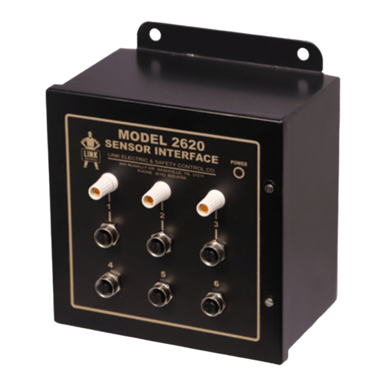
Page 5: Introduction
• The enclosure of the Sensor Interface features a removable bulkhead that can be fitted with a quick connection receptacle so that only one cable must be plugged in from the die. Link has an optional standard connector (a 19 pin Turck receptacle suitable for up to 16 channels) or, if desired, a customer supplied connector can be used. -
Page 6: Specifications
Specifications Size: 6.6” X 6.6” X 4.25” deep (Not counting connections on the front or quick connect bulkhead connector) Input Power: 90-264VAC, 47-63Hz, 0.4Amps 24VDC +/- 10%, Up to 10 Amps Unit should be powered by AC power OR DC NOTE: power, Not Both! Sensor Power:... -
Page 7: Installation
The dimensions and mounting footprint of the Sensor Interface are shown below in Figure 2. When mounted to the press frame or other high shock areas, Link highly recommends using the included shock mounts, which will add about 0.75 inches (19mm) to the depth of the unit. -
Page 8: Wiring
Power Supply BOTTOM ROW: SENSOR CONNECTIONS Power Jumper Figure 3: 2620 Sensor Interface Internal Features 2.1.1 Power Wiring WARNING: National Codes and standards (NEC, VDE, BSI, etc.) and local codes outline provisions for safely installing electrical equipment. Installation must comply with specifications regarding wire types, conductor sizes, branch circuit protection, and disconnect devices. -
Page 9: Internal Sensor Connector Wiring
Connector sensors that are always present on the machine regardless of what die is installed. Link offers (Link PN 109090) an optional quick connect bulkhead connector (using a Turck CS-19 connector) that is prewired and ready to plug into the Internal Sensor Connector. -
Page 10: Front Panel Sensor Connectors
These are wired to match the typical industry standard 2 or 3 wire DC sensors with molded M12 connectors. M12 connectors are also available (Link PN 108046) that can be wired in the field. Figure 5 at right shows the pinout and typical connection for the M12 connector.
Need help?
Do you have a question about the 2620 and is the answer not in the manual?
Questions and answers