
Summary of Contents for J&D MAnufacturing JDN4-5
- Page 1 JDN4‐5 J&D Manufacturing © 2016 Rev: 01 ‐ 21 &D Manufacturing • • • www.jdmfg.com IS255‐21A Eau Claire, WI 54701 1‐800‐998‐2398...
- Page 2 ...
-
Page 3: Table Of Contents
Introduction This user’s guide is for the installation and use of the JDN4‐5 system. Contents Introduction ……………………………………………………………………………………………………………………………………………………. 1 Contents …………………………………………………………………………………………………………………………………………………………. 1 The JDN4‐5 System …………………………………………………………………………………………………………………………………………. 3 Main Features …………………………………………………………………………………………………………………………….. 3 Section 1 – Electrician’s Guide …………………………………………………………….…………………………………………………………. 4 Chapter 1 ‐ Installing the JDN4‐5 System …………………………………………………………………………………………………… 4 Supplying Power to the JDN4‐5 System ………………………………………………………………………………. 4 Chapter 2 – Temperature Sensor Installation ……………………………………………………………………………………………. 5 Placing the Temperature Sensors ……………………………………………………………………………………….. 5 Extending the Temperature Sensor ……………………………………………………………………………………. 5 Chapter 3 – Rain Sensor Installation ………………………………………………………………………………………………………….. 6 Decide Location of Rain Sensor …………………………………………………………………………………………… 6 Rain Sensor Sensitivity Adjustment ……………………………………………………………………………………. 7 Connecting the Rain Sensor to the JDN4‐5 …………………………………………………………………………. 8 Controlling Multiple Curtains with a Single Rain Sensor …………………………………………..….…….. 9 Rain Sensor Troubleshooting ……………………………………………………………………………………………… 9 Chapter 4 – Curtain Motor Load Sensor Installation ………………………………………………………………………………… 10 Chapter 5 – Wind Meter Installation ……………………………………………………………………………………………………….. 11 Chapter 6 –Curtain Motor Wiring ……………………………………………………………………………………………………………. 12 DC Curtain Motors ……………………………………………………………………………………………………………. 12 AC Curtain Motors ……………………………………………………………………………………………………………. 13 Curtain Motors Troubleshooting ………………………………………………………………………………………. 14 Curtain motors do not run ……………………………………………………………………………….. 14 Troubleshooting Relays ……………………………………………………………………………………. 14 Emergency Latching of Output Relays …………………………………….……………………………………….. 14 Electrician Checklist ………………………………………………………………………………………………………………………………… 15 &D Manufacturing • • • www.jdmfg.com P a g e | 1 ... - Page 4 Section 2 ‐ User Guide …………………………………………………………………………………………………………………………………… 17 Overview of the Screen and Buttons ………………………………………………………………………………………………………. 18 Parameters …………………………………………………………………………………………………………………………………………….……… 18 Viewing and Changing Parameters ………………………………………………………………………………………….. 18 Curtain Parameters …………………………………………………………………………………………………………………………………. 19 Understanding Curtain Temperature Parameters …………………………………………………………………….. 19 Understanding Curtain Cycle Time ……………………………………………………………………………………………. 19 Understanding Rain Sensor Perimeters …………………………………………………………………………………….. 20 Troubleshooting & Amp Overload …………………………………………………………………………………………….. 20 General Configuration parameters ………………………………………………………………………………………………………… 21 Fans …………………………………………………………………………………………………………………………………………… 22 Fan Parameters ………………………………………………………………………………………………… 22 When should I start my fans? ………………..…………………………………………………………. 23 Variable Speed Fans …………………………………………………………………………….………….. 23 Sprinklers ……………………………………..…………………………………………………………………………………………… 25 Sprinkler/soaker information …………………………………..………………………………………. 25 What sprinklers do …………………………………………………………………………………………… 25 When should the sprinklers turn on? ……………………………………………………………….. 26 How much water should I spray on the cows …………………………………………………… 26 What is the dryoff time ……………………………………………………………………………….….. 27 Effective Temperature ………………………………………………………………………………………………………………………….…. 27 Heaters ……………………………………………………………………………………………………………………………………………………. 28 ...
-
Page 5: The Jdn4-5 System
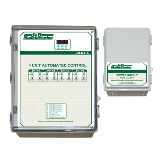
The JDN4‐5 System Thank you for purchasing the JDN4‐5 System. The JDN4‐5 is designed for easy installation and operation. The system controls 8 stages of curtains, fan or sprinklers. Main Features The JDN4‐5 System is designed for the unique challenges of livestock facilities. Controls up to four individual curtains, or up to 6 fans or 8 sprinkler zones Each of the curtain circuits has its own temperature setting. Has adjustable open and shut temperature. Rain sensors for two curtains circuits. (Optional) Has toggle switch overrides for all output relays Effective temperature compensation JDN4‐5 with power supply for DC curtain motors Rain sensor &D Manufacturing • • • www.jdmfg.com P a g e | 3 IS255‐21A Eau Claire, WI 54701 1‐800‐998‐2398... -
Page 6: Chapter 1 - Installing The Jdn4-5 System
– ’ ECTION LECTRICIAN S UIDE Chapter 1 ‐ Installing the JDN4‐5 System Consider the following before installing the JDN4‐5 System: Protect the enclosures from moisture—mount them in a secure and dry place. Place JDN4‐5 and power supply where cows are not be able to come in contact with them. Important: Only drill holes in the bottom of the enclosures. Drilling holes into the top of the enclosures voids the warranty. Supplying Power to the JDN4‐5 System Power the system with 120 VAC as shown in Image 1. Installing surge protection back at breaker panel is recommended. Image 1 &D Manufacturing • • • www.jdmfg.com ... -
Page 7: Chapter 2 - Temperature Sensor Installation
Chapter 2 ‐ Temperature Sensor Installation Placing the Temperature Sensors Place the temperature sensor in the middle of the barn or in a location which represents the barns average temperature. Note: It is important to not allows sensors to come into contact with direct sunlight Extending the Temperature Sensor The sensor that’s included is 10 feet long. If you extend it, do the following: 1. Run a length of 18‐24 AWG wire (twisted or shielded if possible) from the temperature sensor to the JDN4‐5. Keep the sensor wire away from high voltage wire by at least 1 foot. 2. Solder or use gel filled crimps to connect the wires to the temperature sensor. 3. After connection is complete, make sure it is waterproof. 4. Connect the temperature sensor to the JDN4‐5 as shown below in Image 2: Image 2 &D Manufacturing • • • www.jdmfg.com P a g e | 5 IS255‐21A Eau Claire, WI 54701 1‐800‐998‐2398... -
Page 8: Chapter 3 - Rain Sensor Installation
Chapter 3 ‐ Rain Sensor Installation Rain sensors are optional. For individual curtain response pair each curtain with its own rain sensor or use a single rain sensor to control multiple curtains. Decide Location of Rain Sensor The curtain closes whenever its rain sensor detects precipitation. The location/height of the rain sensor compared to your eave, is the rain response mechanism. Use Image 3 and the following steps to determine where to mount the sensor. Visualize rain falling straight down from the edge of the eve. Visualize wind beginning to blow the rain towards the sidewall. As wind increase, it blows the rain in the barn at an increasing height. Decide at what height the rain is unacceptable. Mount the sensor at that height, with the sensor tilted slightly away from the barn. Note: If bedding or other debris can accumulates on the sensor, it may not work until its gets washed off Image 3 &D Manufacturing • • • www.jdmfg.com P a g e | 6 ... -
Page 9: Rain Sensor Sensitivity Adjustment
Rain Sensor Sensitivity Adjustment Image 4 &D Manufacturing • • • www.jdmfg.com P a g e | 7 IS255‐21A Eau Claire, WI 54701 1‐800‐998‐2398... -
Page 10: Connecting The Rain Sensor To The Jdn4-5
Connecting the Rain Sensor to the JDN4‐5 The rain sensor comes prewired with a connector and a 3ft color coded pigtail. Wire colors function as follows: Blue = 24 vdc Black = ground Brown = signal ground White = input signal to controller 50 or 100 foot extensions can be purchased. Alternatively, regular 18 awg can be used to extend the sensor. Route the sensor’s wire at least one foot away from 120 volt (or higher) wires. Locate the rain sensor terminal block inside the JDN4‐5. The terminal block has four terminals marked Blue, Black, Brown, and White. Connect the rain sensor cord to terminals as per wire color marked on the rain sensor terminal block. Image 5 rd Connecting the 3 and 4 rain sensors If no wind meter is being used the 3 input terminal can be used as a rain sensor input. rd The 3 & 4 sensor terminals do not provide power due to space limitations on the board. To wire the 3rd and 4th rain sensors, connect the brown (ground) and white (input) wires to the corresponding 3rd and 4th sensor terminal and the black (24v) and blue (ground) wires to sensor terminal #1. &D Manufacturing • • • www.jdmfg.com P a g e | 8 IS255‐21A Eau Claire, WI 54701 1‐800‐998‐2398... -
Page 11: Controlling Multiple Curtains With A Single Rain Sensor
Controlling Multiple Curtains with a Single Rain Sensor Multiple curtains can be operated from a single sensor. To get satisfactory performance, the curtains should be on same side of of the building. Combining top and bottom curtains gives unsatisfactory performance in dairy applications. To connect multiple curtains: Jump the white (input) wire between all curtains that share the sensor. for #3 curtain and the 4 input terminal is available for an additional rain sensor to control the #4 curtain. The 3 and 4 input terminals are not powered, the black and blue wires from the 3 and 4 rain sensor will need to be connected to the Rain Sensor input #1 corresponding terminals. Rain Sensor Troubleshooting: When it senses rains, the sensor will connect brown & white together. When the rain sensors input circuit is activated by rain and closed, the controller will display R1 or the respective sensor number. To show if sensor is working, the sensor has a green LED light in the center of its clear dome. It will illuminate when it detects rain. To tell if sensor is working, dump water on it, and then rub it with wet hands. You will be able to hear it click and see the green LED light as soon as it detects rain. If the green LED light in the rain sensor does not turn on when sensor is tested make sure there is 24vdc between the blue and black wire at the rain sensor. &D Manufacturing • • • www.jdmfg.com P a g e | 9 ... -
Page 12: Chapter 4 - Curtain Motor Load Sensor Installation
Chapter 4 ‐ Curtain Motor Load Sensor Installation The optional curtain motor load sensor monitors the amp load of each motor. By monitoring the amps of the hot wire for the curtain motor power supply, it calculates the amp draw for the motors. Wire the signal wires with 18 to 24 awg as shown below. Wire the power to the curtain motor power supply as shown below. Neutral or L2 does not go through the amp meter. Go directly to curtain motor power supply after you went through the amp meter. Do not power anything else after the amp meter, or it will cause inaccurate amp readings. Image 6 Install the amp meter on Hot or L1 for 240 volt. Pass the 120 hot wire through twice. If you are using 240 volt, pass L1 through 4x. &D Manufacturing • • • www.jdmfg.com P a g e | 10 IS255‐21A Eau Claire, WI 54701 1‐800‐998‐2398... -
Page 13: Chapter 5 - Wind Meter Installation
Chapter 5 ‐ Wind Meter Installation The wind meter shuts the fans off when it is windy outside. Mount the wind meter up above the roof or inside the building. If you mount it inside, make sure the fans will not affect it. Wire the wind meter as shown in diagram. Polarity is not important. The screens left most decimal point is the wind meter indicator light. The leftmost decimal point will blink as the wind meter rotates. The blinking decimal point is how you verify the wind meter is connected correctly. Image 7 &D Manufacturing • • • www.jdmfg.com P a g e | 11 IS255‐21A Eau Claire, WI 54701 1‐800‐998‐2398... -
Page 14: Chapter 6 -Curtain Motor Wiring
Chapter 6 – Curtain Motor Wiring The JDN4‐5 System was designed to allow multiple curtain motors to be easily wired. The curtain motors switch on one at a time. This allows multiple motors to be wired from a single power source. DC Curtain Motors The following schematic shows how to wire multiple DC curtain motors. Image 8 The following are the maximum recommended wire lengths based on wire gauge for the J&D DC curtain drives. For all other drives refer to the motor manual for recommendations. PCSR120 PCSR250 J&D’s 120W DC curtain drive wiring specs J&D’s 250W DC curtain drive wiring specs 120’ if using 12 AWG wire 100’ if using 12 AWG wire 200’ if using 10* AWG wire 160’ if using 10* AWG wire 300’ if using 8* AWG wire 250’ if using 8* AWG wire * Wire heavier than 12 AWG will require a spade lug terminal to connect the wire to the relay &D Manufacturing • • • www.jdmfg.com P a g e | 12 IS255‐21A Eau Claire, WI 54701 1‐800‐998‐2398... -
Page 15: Ac Curtain Motors
AC Curtain Motors The even numbered relays are energized for CLOSE and odd numbered relays are energized for OPEN. Note: If the curtain motor is more than 1/3 HP, use an external contactor to switch the curtain motor current. Image 9 &D Manufacturing • • • www.jdmfg.com P a g e | 13 IS255‐21A Eau Claire, WI 54701 1‐800‐998‐2398... -
Page 16: Curtain Motors Troubleshooting
Curtain Motors Troubleshooting “The curtain motors do not run” For 24 VDC curtain motors the power supply fuse may have blown. Check the fuse in the curtain motor power supply box. Check if there is voltage coming from the power supply. For AC curtain motors, check the fuse breaker supplying the curtain motors. A relay may be burned out. Other Possible Issues “An output relay seems burned out” The output relays can burn out and still show their indicator light on. Swap relays to see if you can replicate the problem in another circuit. Replace relays with Magnecraft 24 vdc coil 781 series Troubleshooting the relays You can verify if the controller and its wiring by using the relay board diagnostics. The diagnostics allow you to turn the relays on one at a time via the keypad. This is so we can tell if toggle switches and other components are working. To turn the relays on via the keypad: Turn power off to the JDN4‐5, wait 10 seconds Press the Down while repowering the JDN4‐5. The screen will now show 01. This means relay #1 is selected. Press Enter to turn the relay on. Press UP/Down to select other relays. Emergency Latching of Output Relays The output relays in the System can be manually activated. This function allows the ventilation JDN4‐5 equipment to be tested and operated even if the controller is not powered (curtain power supply must still be powered). Manually Activating an Output Relay To manually operate the relay, press and hold the green button as shown in Image 10. Release when curtain is at desired position. ... - Page 17 &D Manufacturing • • • www.jdmfg.com P a g e | 15 IS255‐21A Eau Claire, WI 54701 1‐800‐998‐2398...
- Page 18 &D Manufacturing • • • www.jdmfg.com P a g e | 16 IS255‐21A Eau Claire, WI 54701 1‐800‐998‐2398...
-
Page 19: Section 2 - User Guide
SECTION 2 ‐ USER GUIDE &D Manufacturing • • • www.jdmfg.com P a g e | 17 IS255‐21A Eau Claire, WI 54701 1‐800‐998‐2398... -
Page 20: Overview Of The Screen And Buttons
Overview of the Screen and Buttons The temperature is displayed on the screen whenever the parameters are not being assessed. The figure below (Image 11) shows that its 60˚. If a rain sensor is connected and is sensing rain, the screen will blink for curtain #1 or if it is sensing rain for curtain #2. E‐1 E‐4 The screen will blink thru , if a curtain motor tripped the electronic overload. E‐1 E‐2 Enter is for 1 motor; is for 2 motor. Press to clear. Why does my temperature flash sometimes? The screen will flash the Effective temperature when it’s activated. Effective temperature is automatically activated when controller thinks it’s been extra hot. Image 11 Parameters There are several parameters that you can change. The parameters are labeled , …. These parameters are the curtain’s temperature setpoints and cycle time. Viewing and Changing Parameters Enter To view the first parameter, press . The screen now alternates between and parameter ... -
Page 21: Curtain Parameters
Curtain Parameters Understanding Curtain Temperature Parameters The temperature setpoint for each curtain controls when the curtain opens. If the temperature is warmer than the setpoint the curtain will slowly open. The temperature must drop several degrees below the setpoint before the curtain will slowly close. The temperature deadspan controls how much the temperature must drop before the curtains begin to close. Understanding Curtain Cycle Time The curtains use a cycle to control how fast they respond to temperature changes. The cycle consists of On seconds and wait minutes. The curtain switches on for P6 seconds and then waits for P7 minutes then repeats the cycle. Adjust the cycle time so the curtain takes approximately one hour to fully open or close. Parameter Table 1 ID Description Default Min Max P1 Curtain #1 temperature setpoint 60° 1° 99° P2 Curtain #2 temperature setpoint 60° 1° 99° P3 Curtain #3 temperature setpoint 60° 1° 99° P4 Curtain #4 temperature setpoint 60° 1° 99° ... -
Page 22: Understanding Rain Sensor Perimeters
Understanding Rain Sensor Parameters The rain sensor closes the curtains when rain is sensed on the sensor element. You control how much rain shuts the curtain by the location the sensor is mounted and by adjusting the sensitivity knob inside the rain sensor. Anytime rain is sensed the curtain will close for a maximum of approximately 3 minutes [parameter C3]. As soon as the rain is no longer sensed, the curtain will try to reopen. Troubleshooting & Amp Overload E‐1 E‐4 If your screen is flashing thru one of your curtains is tripped the amp overload. The amp overload stops a motor if the amps climb to high. This curtain will not go again from temperature until you clear it. The remaining curtains will continue working. Even if a curtain is overloaded you can force it by using the toggle switches. Take care when doing this. You may be able to figure out the problem by forcing the curtain. Force it to go open. While it’s running, watch the amp reading on the screen. If it spikes near the top, the top limit is not set correctly. My curtain overloads all the time. However the curtain still moves. If a curtain overloads every couple of days or less, you may have a problem. It could be the limit switch on the motor is not stopping the curtain until it’s wrapped too tight or a rope, strap or weeds are wrapped in the curtain. My curtain overloads quickly. Curtain does not move. You curtain motor maybe bad. Also check for damaged cords around the motor. Tech note: The controller does not consider the motor overloaded the first time the amps spike above the curtain’s setpoint. It will try multiple times. It tries multiple times until it decides the motor is overloaded for real. Default is set to try twice. Example: If curtain tries to open, and draws too may amps then the curtain tries to open a second time and again draws too many amps the curtain will be overloaded for Open. After a while the curtain may try to close, if the motor can jog close, it will clear the overload. Now the curtain can go open again. &D Manufacturing • • • www.jdmfg.com P a g e | 20 ... -
Page 23: General Configuration Parameters
General Configuration Parameters There are several configuration parameters which change the way the controller operates. To access Enter the configuration menu, remove the power from the controller and repower while pressing . Table 2 Parameter Description Default Min Max ID C1 Number of curtains for this controller 0 4 C2 Number of fan banks for this controller 0 6 C3 Number of sprinkler circuits for this controller 0 8 C4 0= Fahrenheit , 1=Celsius 0 0 1 C5 Max seconds the curtain will close when the 180 10 255 curtain senses rain. C6 MPH deadspan for fans 3.5 ... -
Page 24: Fans
C18 Amp meter averaging. How many internal 8 1 255 Table 2 readings are averaged, so you have a more Continued stable amp number. Higher = more stable but slower reacting. C19 (Only active if there is a 2 temperature 0 0 4 sensor) How many curtains will use the 2 sensor starting with curtain#1 Future C21 When raining , which curtain must close 0 0 4 before curtain#1 may close C22 When raining , which curtain must close 0 0 4 before curtain#2 may close ... -
Page 25: When Should I Start My Fans
P29 MPH at which the fans will turn off. With 12 3 60 Table 3 optional wind meter. Continued If you have open sidewalls, and its really windy outside, you can save electric by having your fans turn off automatically. P30 Duty cycle, off minutes. (For cold weather 2.0 .1 25.5 ventilation** P31 Duty cycle, on minutes ( For cold weather 2.0 .1 25.5 ventilation)** * Note: All the fan banks use the Effective temperature, which can be warmer than ambient°. **Hidden if not used. The duty cycle, will cycle a fan bank on and off, when fan would normally be off. The duty cycle can be applied to fan bank #1 or #2. See configuration menu to activate the duty cycle. When should I start my fans? ... - Page 26 Table 4 Parameter ID Description Default Min Max P35 Begin accelerating temperature. When 60º 1º 120º temperature° gets warmer than this, the fans begin to spin faster. Below this, the fans will spin at constant rate until their circulating fan relay turns off. P36 Full speed temperature. When 95º 1° 120º temperature reaches this, the fan will be full throttle. Note: the speed ramps with the temperature. (It does not jump from low to full speed) P37 Minimum fan speed, the slowest the fans 15.0% 1% 100% will run, in % of full speed P38 Manual override speed. This allows you to 11(auto) 1 10 fix the fans speed indefinitely. Set it to 11 for automatic temperature control. Manually force it to a fixed speed by setting it between 0‐10. 0 is off and 10 is full speed. ...
-
Page 27: Sprinklers
Sprinklers The controller operates up to 8 sprinkler circuits. You adjust the temperature when they start spraying and how often it sprays. As it gets hotter it will spray more often. You can adjust all this. Parameter ID Description Default Min Max Table 5 P40 Low /on temperature. Sprinklers turn on at 75º 1º 120º this temperature. P41 The high temperature for sprinklers. 95º 1° 120º P42 Dry off / interval minutes at low 15.0 .1 25.5 temperature P43 Dry off / interval minutes at High 5.0 .1 25.5 temperature P44 Sprinkler #1 sprinkle seconds at Low 30 1 255 temperature P45 ... -
Page 28: When Should The Sprinklers Turn On
When should the sprinklers turn on? The sprinklers are often turned on around 70°F. This default is a good temperature setting to start with. Parameter “P40 sprinkler low temp” controls when the sprinklers begin to cycle. How much water should I spray on the cows The idea of soakers is to spray water onto the cow until she is wet. You may wonder, how do I know if she is wet enough? It is easy to determine this once you have your sprinkler system installed. You get a stopwatch and watch as the water is spraying. When she becomes saturated and the water begins to run off, that is the maximum wetness you can get. Record the length of time it took. You need to make sure that her udder is not getting wet. Refer to Image 13 and Image 14 below for the proper wetness. Here you can see that the water has not wetted the cow's udder. Soaking the cow but not her udder is the goal. Image 14 Image 13 Often the time needed to wet the cow is approximately 30 seconds. This varies considerably by nozzle sizes and water pressure. The default setting is 30 seconds, Parameters P44‐P47 allow you to adjust each sprinkler zones spray time. You can adjust the system to spray more water when it’s hotter. However, proper wetness does not vary significantly by temperature. Now you know how wet to make the cow. You also know where to adjust the spray time. &D Manufacturing • • • www.jdmfg.com P a g e | 26 IS255‐21A Eau Claire, WI 54701 1‐800‐998‐2398... -
Page 29: What Is The Dryoff Time
What is the dryoff time Now you will learn about the dryoff time. The dryoff time is how long the controller waits until it may spray again. The cow is supposed to dryoff before she gets wet again. How quickly the cows dries off really varies with the temperature. As it gets warmer, your cows will dryoff sooner. To accommodate this, the default dryoff time ramps lower and lower as the temperature increases. This makes your sprinklers spray more often as the day gets warmer. Adjusting dryoff The dryoff time default is 15 minutes at 70° and 5 minutes at 90°. This is what the industry feels is a good number to begin using your system. However, if your cows are not drying in the default time, you can change it. To change the dryoff time, Parameter “P42” sets the 70° dryoff time. Parameter “P43” sets the 90° dryoff time. Effective temperature When you have an extra hot day, and it cools at night, your cow needs extra time to cool down. For optimum production and breeding, the JDN4‐5 calculates an effective temperature. The effective temperature is patterned after your cow’s body temperature. It makes your fans and sprinklers run longer after a hot day. Effective temperature keeps a running average of the past 12 hours temperature readings. Then, if the average is above 75°, it assumes the cows need more time to cool. This assumption, adds 5° to the ambient temperature. This is the Effective temperature. The fans and sprinkler use it. You can adjust the 12 hours, the 75° and 5°. P52 is the 75°, the temperature at which it assumes cows are overheated P53 is the 5°, how much the controller adds to the ambient° P54 is 12 hours, how many hours of temperature readings are being considered. C12 allows you turn the effective temperature off for the sprinklers. (See configuration menu Table 2) Parameter ID Description Default Min Max Table 6 P52 Running average temperature at which 74º 1º 120º controller assumes it has been extra hot P53 Degrees added to ambient temperature to 6° 0° ... -
Page 30: Heaters
Heaters You can use the JDN4‐5 to turn heaters on and off. Parameter ID Description Default Min Max Table 7 P60 Heater #1 setpoint temperature 60 1º 99º P61 Heater #2 setpoint temperature 6° 0° 20° P68 Heater hysteresis. A heater set to 75° with 1.0 .1 9.9 a 1.5° hysteresis will turn on at 75.0° and off at 76.5° Update Log: Version 10.2 11‐2012, Input #4 is now programmed to be the rain sensor for curtain #4. Wind wheel input automatically turns its self into curtain rain sensor connection #3, when C1 (number of curtains) is 4. Changed display so it does not display effective temperature if there are zero fans or sprinklers. V10.9 – added heater logic. You can have up to 8 heaters &D Manufacturing • • • www.jdmfg.com ...