Table of Contents
Advertisement
Quick Links
Advertisement
Table of Contents

Summary of Contents for gen2 OTIS OI-6940-NXP Series
- Page 3 CAUTION CAUTION: FOR SAFETY REASONS, THIS EQUIPMENT MUST BE OPERATED AND SERVICED BY QUALIFIED PERSONNEL ONLY. READ AND UNDERSTAND THE INSTRUCTION MANUAL COMPLETELY BEFORE OPERATING OR SERVICING. DANGER DANGER: OTIS INSTRUMENTS INC. OI-6940-X-X-NXP-X IS AN AMBIENT AIR TOXIC GAS SENSOR ASSEMBLY AND ONLY MONITORS IN THE IMMEDIATE VICINITY OF THE SENSOR HOUSINGS.
-
Page 5: Table Of Contents
TABLE OF CONTENTS TABLE OF CONTENTS PRODUCT OVERVIEW ............................1 INTRODUCTION ..............................1 PRODUCT SPECIFICATIONS ..........................2 SYSTEM DIAGRAMS ............................. 3 1.3.1 EXTERNAL SYSTEM DIAGRAM ........................... 3 1.3.2 INTERNAL SYSTEM DIAGRAM..........................4 INSTALLATION AND START-UP .......................... 5 PRODUCT PLACEMENT ............................5 PRODUCT MOUNTING ............................ - Page 6 TABLE OF CONTENTS PRODUCT MAINTENANCE..........................36 SCHEDULED MAINTENANCE ..........................36 SENSOR REPLACEMENT ........................... 37 BACKUP BATTERY REPLACEMENT ........................38 PRODUCT FAULT CODES ..........................39 PRODUCT REPLACEMENT PARTS AND ACCESORIES .................. 40 APPENDIX A: PRODUCT WARRANTY STATEMENT ......................42 APPENDIX B: INFORMATION ABOUT RMA SERVICE REPAIRS ..................44 APPENDIX C: INFORMATION ABOUT RMA RETURNS FOR CREDIT ..................
-
Page 7: Product Overview
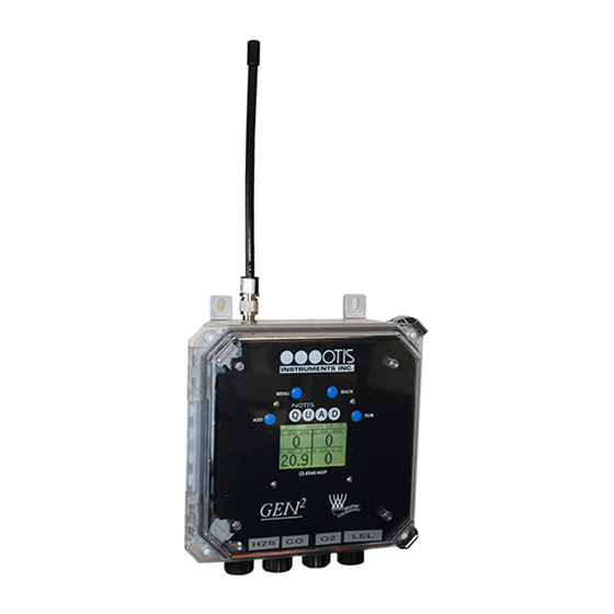
INSTALLATION AND START-UP 1 PRODUCT OVERVIEW 1.1 INTRODUCTION The Otis Instruments, Inc. (Otis) GEN II Model OI-6940-X-X-NXP-X (OI-6940) Non-Explosion-Proof Ambient Air Quad Toxic Gas Detector is designed to detect a wide range of toxic gases in many environments. The OI-6940 features non-intrusive magnetic switches that allow for complete system configuration, regular calibration, and product maintenance to be performed in the field without opening the lid and breaking the seal of the enclosure. -
Page 8: Product Specifications
INSTALLATION AND START-UP 1.2 PRODUCT SPECIFICATIONS System Specifications Operating Voltage 100-240 VAC 0.35A Power Supply Input 3.3 VDC Power Supply Output Battery Life Up to 6 months, 45 days Max with VOC sensor installed (When used as primary power source) Operating Temperature -40⁰C to +54⁰C Range... -
Page 9: System Diagrams
INSTALLATION AND START-UP 1.3 SYSTEM DIAGRAMS Refer to the following diagrams for identification of the external and internal system components that may be referred to in this manual. 1.3.1 EXTERNAL SYSTEM DIAGRAM Radio Antenna – 900 MHz or 2.4 GHz 11 ADD Magnet Button Location 12 MENU Magnet Button Location Enclosure Mounting Foot (4X) -
Page 10: Internal System Diagram
INSTALLATION AND START-UP 1.3.2 INTERNAL SYSTEM DIAGRAM Enclosure Lid (Clear) Front Panel Antenna Fitting Connector Radio Module – 900Mhz or 2.4 GHz Backup Battery Pack Plug External Antenna Fitting AC Power Supply Terminal Board Assembly Backup Battery Pack 10 Battery Pack Restraining Strap 11 Sensor Housing Interface Boards –... -
Page 11: Installation And Start-Up
INSTALLATION AND START-UP 2 INSTALLATION AND START-UP 2.1 PRODUCT PLACEMENT The installation instructions, and any other information supplied by Otis, provide only basic guidelines relating to the properties of toxic gas and the effects of environmental conditions on the OI-6940 device. Sensor placement should be determined in consultation with the site safety personnel, as well as those knowledgeable of: (1) the site/facility where the equipment is being installed and (2) the potentially present gas types and their dispersion. -
Page 12: Product Mounting
INSTALLATION AND START-UP 2.2 PRODUCT MOUNTING It is recommended to mount the unit to a solid structure (Such as a concrete wall, steel column, or angle iron) where a minimum of vibration will be transmitted to the unit. Any style of bolt or screw may be used as long as it is steel and meets or exceeds the following: Maximum 1/4"... -
Page 13: Connecting Ac Power
INSTALLATION AND START-UP 2.3.2 CONNECTING AC POWER The OI-6940 is shipped with an AC power cord for connection to a standard wall outlet supplying 120VAC. An alternate AC power source connection can be used in place of the standard power cord, the instructions below detail the wiring instructions if this change is desired. -
Page 14: Connecting The Battery Pack
INSTALLATION AND START-UP 2.3.3 CONNECTING THE BATTERY PACK The OI-6940 is shipped with the battery pack installed but disconnected from the terminal board. The battery pack is used as a backup supply in case of loss of AC power, but is also capable of fully operating the OI-6940 if an AC power source is unavailable. -
Page 15: System Start-Up
INSTALLATION AND START-UP 2.4 SYSTEM START-UP After power is applied, the unit will enter into OFF mode. Once the enclosure is properly closed you may turn the unit on and begin its 1 minute, 3 ½ minutes when the Low Power Infrared sensor is installed, warmup period. During warmup, the display will show a countdown of the time remaining until the system start-up is complete. -
Page 16: Normal Operating Mode
INSTALLATION AND START-UP 2.5 NORMAL OPERATING MODE During normal operating mode, the OI-6940 continuously samples the air and updates the measured concentration of the target gasses on the display screen. The display, when in normal operation, appears as shown below. ⑦... -
Page 17: Product Settings And Configuration
OPERATION SETTINGS 3 PRODUCT SETTINGS AND CONFIGURATION The product settings and configuration menus allow the end-user to tailor the device settings of the OI-6940 to meet their required specifications and/or site conditions. While the device is in normal operating mode, Press and Hold the MENU button, for approximately 6 seconds, until the product settings and configuration menu is activated and open on the display screen. -
Page 18: Global Settings
OPERATION SETTINGS 3.1 GLOBAL SETTINGS Use the MENU button for SELECT to enter the Global Settings Menu, any settings under this menu option will affect all aspects of the OI-6940. Use the ADD button for NEXT to advance to the Sensor 1 Settings menu. Use the SUB button for PREV to move to the EXIT menu option. -
Page 19: Unit Information
OPERATION SETTINGS 3.1.2 UNIT INFORMATION Press the MENU button for SELECT to enter the Information Screen menu. Use the ADD button for NEXT to advance to the Screen Contrast Menu. Use the SUB button for PREV to move to the Network I.D. menu option. You can also use the BACK button on the OI-6940 to return back to the Main Product Settings and Configuration Menus. -
Page 20: Display Screen Contrast Setting
OPERATION SETTINGS 3.1.3 DISPLAY SCREEN CONTRAST SETTING Press the MENU button for SELECT to enter the Contrast Setting menu. Use the ADD button for NEXT to advance to the Return to Factory Defaults menu option. Use the SUB button for PREV to move to the Information Screen menu option. -
Page 21: Return To Factory Default Settings
OPERATION SETTINGS 3.1.4 RETURN TO FACTORY DEFAULT SETTINGS Press the MENU button for SELECT to enter the Return to Factory Defaults menu. Use the ADD button for NEXT to advance to the Back menu option. Use the SUB button for PREV to move to the Screen Contrast menu option. You can also use the BACK button on the OI-6940 to return back to the Main Product Settings and Configuration Menus. -
Page 22: Back Menu
OPERATION SETTINGS If YES is selected to return the device to its factory default settings: 1. Press the ADD button for YES to confirm that you want to reset the device to its factory default settings. If you do not wish to return the device to its factory default settings, press the SUB button for NO to leave the factory default settings menu and to return to the Global Settings menu. -
Page 23: Sensor Settings
OPERATION SETTINGS 3.2 SENSOR SETTINGS Use the MENU button for SELECT to enter the Sensor 1 Settings Menu, any settings under this menu option will only affect the first sensor element of the OI-6940. Use the ADD button for NEXT to advance to the Sensor 2 Settings menu. -
Page 24: Nulling The Sensor (Auto Null)
OPERATION SETTINGS The sensor ON/OFF state should only need to be configured in the field if a Return to Factory Defaults occurs. However, you can turn OFF a sensor if that gas type is not needed for a particular location or you are waiting on a replacement sensor element. - Page 25 OPERATION SETTINGS 1. Press the ADD button for YES to confirm that the sensor is in clean air and to begin nulling the sensor. If the sensor is not in clean air, press the SUB button for NO to discontinue the null process and return to the start of the Null process.
-
Page 26: Calibrating The Sensor (Manual Cal)
OPERATION SETTINGS 3.2.3 CALIBRATING THE SENSOR (MANUAL CAL) Press the MENU button for SELECT to enter the Sensor Cal menu. Use the ADD button for NEXT to advance to the Sensor Radio Address menu option. Use the SUB button for PREV to move to the Sensor Null menu option. You can also use the BACK button on the OI-6940 to return back to the Main Product Settings and Configuration Menus. -
Page 27: Calibrating The Sensor (Auto Cal)
OPERATION SETTINGS 5. When calibration is complete, detach the Calibration Adapter Kit from the sensor housing and reaffix the sensor housing cap. Press the MENU or BACK button to return to the Sensor Settings Menu. 3.2.4 CALIBRATING THE SENSOR (AUTO CAL) If you calibrated the sensor manually this section may be skipped and you can continue to section 3.2.5. - Page 28 OPERATION SETTINGS 2. Press the ADD button to select YES to confirm that you want to calibrate the sensor and to continue to the concentration setting screen. If you do not wish to continue to calibrate the sensor, press the SUB button to select NO and return to the Sensor Settings Menu.
- Page 29 OPERATION SETTINGS NOTICE Once the calibration countdown has started, the process cannot be stopped without disconnecting the power sources. If the sensor responds extremely slow, or does not respond to the applied gas, it may indicate a failed sensor element. The sensor element will need to be replaced before completing the null and calibration process. 8.
-
Page 30: Sensor Radio Address
OPERATION SETTINGS 3.2.5 SENSOR RADIO ADDRESS Press the MENU button for SELECT to enter the Sensor Radio Address menu. Use the ADD button for NEXT to advance to the Sensor Relay Test menu option. Use the SUB button for PREV to move to the Calibrate Sensor menu option. -
Page 31: Sensor Relay Test
OPERATION SETTINGS 3.2.6 SENSOR RELAY TEST Press the MENU button for SELECT to enter the Sensor Relay Test menu. Use the ADD button for NEXT to advance to the Sensor Background Setting menu option. Use the SUB button for PREV to move to the Sensor Radio Address menu option. -
Page 32: Sensor Background Setting
OPERATION SETTINGS 3.2.7 SENSOR BACKGROUND SETTING Press the MENU button for SELECT to enter the Sensor Background Setting menu. Use the ADD button for NEXT to advance to the Calibration Method Setting menu option. Use the SUB button for PREV to move to the Sensor Relay Test menu option. -
Page 33: Sensor Background High Setting
OPERATION SETTINGS 3.2.8 SENSOR BACKGROUND HIGH SETTING Press the MENU button for SELECT to enter the Sensor Background High Setting menu. Use the ADD button for NEXT to advance to the Background Low Setting menu option. Use the SUB button for PREV to move to the Sensor Relay Test menu option. -
Page 34: Sensor Background Low Setting
OPERATION SETTINGS 3.2.9 SENSOR BACKGROUND LOW SETTING Press the MENU button for SELECT to enter the Sensor Background Low Setting menu. Use the ADD button for NEXT to advance to the Calibration Method menu option. Use the SUB button for PREV to move to the Sensor Background High Setting menu option. -
Page 35: Calibration Method
OPERATION SETTINGS 3.2.10 CALIBRATION METHOD Press the MENU button for SELECT to enter the Calibration Method Setting menu. Use the ADD button for NEXT to advance to the Sensor Information menu option. Use the SUB button for PREV to move to the Sensor Background Setting menu option. -
Page 36: Sensor Information
OPERATION SETTINGS 3.2.11 SENSOR INFORMATION Press the MENU button for SELECT to enter the Sensor Information menu. Use the ADD button for NEXT to advance to the Last Null & Cal Times menu option. Use the SUB button for PREV to move to the Calibration Method Setting menu option. -
Page 37: Null-Calibration Timer Information
OPERATION SETTINGS 3.2.12 NULL-CALIBRATION TIMER INFORMATION Press the MENU button for SELECT to enter the Last Time Null & Cal Times menu. Use the ADD button for NEXT to advance to the Reset Sensor Null/Cal menu option. Use the SUB button for PREV to move to the Sensor Information menu option. -
Page 38: Reset Sensor Null/Cal
OPERATION SETTINGS 3.2.13 RESET SENSOR NULL/CAL Press the MENU button for SELECT to enter the Reset Sensor Null/Cal menu. Use the ADD button for NEXT to advance to the Back menu option. Use the SUB button for PREV to move to the Last Null & Cal Times menu option. You can also use the BACK button on the OI-6940 to return back to the Main Product Settings and Configuration Menus. -
Page 39: Back Menu
OPERATION SETTINGS 3. If YES was selected the following screen will appear to signal completion of the sensor returning the null and calibration to their defaults. The MENU or BACK button will return you to the Sensor Settings Menu. NOTICE If the sensor element null and calibration are reset to default you MUST then perform the Null and Calibration Processes as outlined in this manual for proper operation of the OI-6940. -
Page 40: Operation Settings
OPERATION SETTINGS 4 OPERATION SETTINGS At the time of installation, when the power is first applied to the OI-6940, the unit automatically enters into OFF mode. Pressing and holding the ADD button begins the startup countdown and warmup period. During the 1 minute warmup, 3 ½ minutes with Low Power Infrared sensor installed, the display will show a countdown of the time remaining until the system start-up is complete. -
Page 41: Display Behavior Above Background
OPERATION SETTINGS 4.2 DISPLAY BEHAVIOR ABOVE BACKGROUND When any sensor is above its configured background gas level the display screen will change to show the readings one sensor assembly at a time. The OI-6940 will scroll among all configured sensor assemblies showing the detected gas level in a larger font. -
Page 42: Product Maintenance
PRODUCT MAINTENANCE 5 PRODUCT MAINTENANCE 5.1 SCHEDULED MAINTENANCE Otis recommends that our equipment be calibrated a MINIMUM of every 90 days, and STRONGLY advise that calibration be performed every 30 days. Without knowing the specific application, sensor assembly location, gas exposure, and other factors, the company recommends monthly calibrations –... -
Page 43: Sensor Replacement
PRODUCT MAINTENANCE 5.2 SENSOR REPLACEMENT The sensor elements used in the OI-6940 detect gas in either % or PPM concentrations, the elements must be fully functional in order for the system to operate correctly. Otis recommends replacing the sensing element whenever a slow response to gas is observed during the normal calibration process. -
Page 44: Backup Battery Replacement
PRODUCT MAINTENANCE 5.3 BACKUP BATTERY REPLACEMENT The backup battery in the OI-6940 should not need to be replaced during normal operation of the unit. If the backup battery is used as the primary power source the battery pack will operate for up to 6 months with normal usage. The presence of gas will increase the radio transmission rate and decrease the battery lifetime. -
Page 45: Product Fault Codes
PRODUCT MAINTENANCE 5.4 PRODUCT FAULT CODES OI-6940 Fault Codes Problem Cause(s) Solution(s) The control board has lost communication with the 1. Replace the sensor element. Check sensor element or sensor housing. 2. Replace the sensor housing. Sensor Board The unit did not null correctly, due to: 1. -
Page 46: Product Replacement Parts And Accesories
PRODUCT MAINTENANCE 5.5 PRODUCT REPLACEMENT PARTS AND ACCESORIES While not all of the components on the OI-6940 can be field-replaced, there are several parts that are replaceable by an Otis Approved Service Technician. To purchase accessories/replacement parts for your device, contact the sales representative of this product for assistance. - Page 47 APPENDICES APPENDICES APPENDIX A: OTIS INSTRUMENTS PRODUCT WARRANTY STATEMENT APPENDIX B: INFORMATION ABOUT RMA SERVICE REPAIRS APPENDIX C: INFORMATION ABOUT RMA RETURNS FOR CREDIT OI-6940-X-X-NXP OPS_GUIDE_REV 1.0...
-
Page 48: Appendix A: Product Warranty Statement
APPENDICES APPENDIX A: PRODUCT WARRANTY STATEMENT Warranty Coverage Otis Instruments, Inc., 301 S. Texas Avenue, Bryan, Texas, 77803 (“Otis”) warrants the manufacture of all Otis hardware, firmware, software, components, and product accessories (“Otis Products”), contained in the original packaging, against defects in materials and workmanship when used normally in accordance with Otis’... - Page 49 APPENDICES Otis Products submitted to Warranty service must be returned in their complete assembly, as originally shipped from the manufacturer. Warranty service will not service/repair Otis Products that are not in their original condition. For Otis Gas Detection Products, also referred to as Sensor Assemblies, the end-user/purchaser must remove external antenna(s), rain guard(s), and all batteries before shipping.
-
Page 50: Appendix B: Information About Rma Service Repairs
APPENDICES APPENDIX B: INFORMATION ABOUT RMA SERVICE REPAIRS Otis Instruments, Inc. offers technical support to our customers. Please contact the Otis Instruments RMA Service Department for technical support, repair requests, warranty inquiries, end-user commission reports, dealer/distributor support, and Modbus setup inquiries and services. This appendix is for information purposes only. - Page 51 APPENDICES INTERNATIONAL RMA SERVICE REPAIRS The customer is responsible for complying with all import/export requirements for shipment of RMA/Service repairs to Otis Instruments, Inc. OTIS INSTRUMENTS RMA SERVICE DEPARTMENT Otis Instruments / Repairs 301 South Texas Ave. Bryan, Texas 77803 Office: 979.776.7700 Fax: 979.776.7719 service@otisinstruments.com...
-
Page 52: Appendix C: Information About Rma Returns For Credit
APPENDICES APPENDIX C: INFORMATION ABOUT RMA RETURNS FOR CREDIT Without exception, all RMA Returns for Credit to Otis Instruments, Inc. must receive prior approval before shipment. Otis Products received that do not have prior approval will be returned (uncredited) COD to the customer. For inquiries and approval for RMA Returns for Credit, please contact your local sales representative. - Page 53 NOTES ________________________________________________________ ________________________________________________________ ________________________________________________________ ________________________________________________________ ________________________________________________________ ________________________________________________________ ________________________________________________________ ________________________________________________________ ________________________________________________________ ________________________________________________________ ________________________________________________________ ________________________________________________________ ________________________________________________________ ________________________________________________________ ________________________________________________________ ________________________________________________________ ________________________________________________________ ________________________________________________________ ________________________________________________________ ________________________________________________________ ________________________________________________________ ________________________________________________________ ________________________________________________________ ________________________________________________________ ________________________________________________________ ________________________________________________________...
- Page 54 NOTES ________________________________________________________ ________________________________________________________ ________________________________________________________ ________________________________________________________ ________________________________________________________ ________________________________________________________ ________________________________________________________ ________________________________________________________ ________________________________________________________ ________________________________________________________ ________________________________________________________ ________________________________________________________ ________________________________________________________ ________________________________________________________ ________________________________________________________ ________________________________________________________ ________________________________________________________ ________________________________________________________ ________________________________________________________ ________________________________________________________ ________________________________________________________ ________________________________________________________ ________________________________________________________ ________________________________________________________ ________________________________________________________ ________________________________________________________...
- Page 56 Otis Instruments 301 S. Texas Avenue, Bryan, Texas 77803 Tel: 979.776.7700 Fax: 979.776.7719 sales@otisinstruments.com service@otisinstruments.com www.otisinstruments.com...
Need help?
Do you have a question about the OTIS OI-6940-NXP Series and is the answer not in the manual?
Questions and answers