Table of Contents
Advertisement
Advertisement
Table of Contents

Related Manuals for SHOTO SDA10-49100


Summary of Contents for SHOTO SDA10-49100
- Page 1 Home power Lithium-Ion Battery Product Manual (V1.0) Shuangdeng Group Co., Ltd...
-
Page 2: Table Of Contents
This manual introduces SDA10-48100 from Shoto. Please read this manual before you to install the battery and follow the instruction carefully during the installation process. Any confusion, please contact Shoto immediately for advice and clarification. Contents 1. Safety Precautions ........................4 1.1、... - Page 3 5.4、NOTE ..........................15 5.5、Safety Gear ........................15 5.6、 Installation ........................16 5.6.1、Package Items ....................... 16 5.6.2、Installat ion Location .................... 19 6. Trouble Shooting Steps......................20 6.1、Problem determination based on: ................20 6.2、Preliminary determination steps: ................20 6.3、The battery cannot be charged or discharged ............21 7.
-
Page 4: Safety Precautions
1. Safety Precautions 1.1、 Reminding 1)It is very important and necessary to read the user manual carefully (in the accessories) before installing or using battery. Failure to do so or to follow any of the instructions or warnings in this document can result in electrical shock, serious injury, or death, or can damage battery, potentially rendering it inoperable. -
Page 5: Warning
1.2 、Warning 1.2.1、Before Using 1) After unboxing, please check product and packing list first, please read the product manual carefully before installation and application,if product is damaged or lack of parts, please contact with the local retailer; 2) It is prohibited to connect the battery and AC power directly; 3)... -
Page 6: Specifications
3. Specifications Model SDA10-48100 Nominal Capacity (kWh) 5.12 Depth of Charge Usable Capacity (Wh) 4.60 Charge Voltage (V) 54.0-56.4 Discharge Voltage (V) 45.0-48.0 Nominal Voltage (V) 51.2 Recommend 50(0.5C) Charge/Discharge Current(A) Max 100 (1C) Communication Port RS485 & CAN Weight (Kg) 41±... -
Page 7: System Panel Instructions
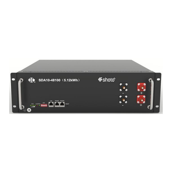
466.4 4. System panel instructions 1 2 3 4 5 6 7 8 Pic.1 SDA10-48100 Schematic of lithium iron battery system panel 4.1、The main information of panel battery products as follows: T able 1 SDA10-48100 The main panel details of lithium iron battery system Number Designation loge... -
Page 8: Communicat Ion Interface
Number Designation loge De scriptions Communication running lights 1 green light running lights Used to set the battery ADD switch correspondence address CAN Communication Terminal: CAN communication port (RJ45 port) follow CAN protocol, for output batteries information Used to communicate with the 485A communication port RS485A computer PC or cascade... - Page 9 Table 2-1 The pins definition of the RS485 port Definitions RS485-B RS485-A RS485-A RS485-B Pic. 2 shows the communication wire with that of DB9 (first wire and sixth wire are not connected).
-
Page 10: Communicat Ion Wire
4.2.2、Communicat ion wire Pic. 3 shows the cascade communication wire connections of RS485. -
Page 11: Can
4.2.3、CAN CAN Communication Terminal:(RJ45 port)follow CAN protocol,for output batteries information。 Table 2-2 The pins definition of the CAN port Definitions CAN-L CAN-H 4.2.4、Power Terminals Power cable terminals: there are two pair of terminals with same function, one connect to equipment, the other one paralleling to other battery module for capacity expanding. -
Page 12: Led Status Indicators
4.2.5、LED Status Indicators 4.2.5.1、LED lights order 1 RUN LED, 1 ALM LED, 4 SOC LED. 4.2.5.3、Capacity indicator Statues Charge Capacity Light 0%~25% Flash 25%~50% Flash Light 50%~75% Flash Light Light 75%~100% Flash Light Light Light Run Light Long lighting Statues Discharge Capacity Light 0%~25%... -
Page 13: Flashing Instructions
50%~75% Light Light Light Light 75%~100% Light Light Light Light Run Light Flashing 4.2.5.4、Flashing instructions Flashing way Light Flash 1 0.25s 3.75s Flash 2 0.5s 0.5s Flash 3 0.5s 1.5s 4.2.5.5、Status indication Remark System Operation status status Dormancy All OFF Shut down Indicating according to actual Normal... -
Page 14: Safe Handling Of Lithium Batteries Guide
5. Safe handling of lithium batteries Guide 5.1、Schematic Diagram of Solution Inverter Public Grid PV Arry Local Load Battery Module BATTERY MODU 5.2、Explanation of Symbol Do not disconnect or disassemble by non- professional personnel. Do not connect the battery pack output positive and negative ports reversely. -
Page 15: Tools
5.3、Tools The following tools are required to install the battery pack. Wire cutter Crimping Modular Plier Screw Driver style ammeter 5.4、NOTE Use properly insulated tools to prevent accidental electric shock or short circuits. If insulated tools are not available, cover the entire exposed metal surfaces of the available tools, except their tips, with electrical tape. -
Page 16: Installation
Safety goggles 5.6、 Installation 5.6.1、Package Items Unpacking and check the Packing List. 1)For battery module package: Two power cables and one communication cable for each battery package: 150mm 150mm 300mm 2)Grounding cable: 1000mm Grounding cables use 10AWG yellow-green cables. - Page 17 Module grounding is based on metal directly touch between the module’s surface and rack’s surface. So it needn’t grounding cables at all. If uses normal rack, it can remove the paint at the corresponding place.Or install a grounding cable to the grounding point of the modules. 3)For battery system connects to inverter: (Need to be purchased separately,or specify s eparately when placing an order)
- Page 18 4)Two long power cables (current capacity 120A) and one communication cable for each energy storage system. 5、Standard plug: SC25-8 terminal 1、Communication line: 4、Cable longitud: Inverter connected to Customize according battery CAN。 to actual order (Two power cables maximum 120A) 3、The length of the wiring harness is 150mm, and the terminals are quickly...
-
Page 19: Installation Location
5)Adjust the ADD Switch as defined in the figure belowe. 5.6.2、Installation Location Make sure that the installation location meets the following conditions: 1)The area is completely water proof. The floor is flat and level. 2)There are no flammable or explosive materials. 3)The ambient temperature is within the range from -5°... -
Page 20: Trouble Shooting Steps
6. Trouble Shooting Steps 6.1、Problem determination based on: 1)Whether the battery can be turned on or not; 2)If battery is turned on, check the red light is off, flashing or lighting; 3)If the red light is off, check whether the battery can be charged/discharged or not. -
Page 21: The Battery Cannot Be Charged Or Discharged
3)Wet Batteries If the battery pack is wet or submerged in water, do not let people access it, and then contact Shoto or an authorized dealer for technical support. 4)Damaged Batteries Damaged batteries are dangerous and must be handled with the utmost care. - Page 22 Damaged batteries may leak electrolyte or produce flammable gas. If such damage occurs, please contact Shoto: global@chinashoto.com.
- Page 23 Shuangdeng Group Co., Ltd. No.999, Tianmu West Road, Jiangyan Economic Development Zone, Taizhou City, JiangSu, China T+ 0086 523-88529865 marketing@chinashoto.com www.shuangdeng.com.cn...
Need help?
Do you have a question about the SDA10-49100 and is the answer not in the manual?
Questions and answers