
Summary of Contents for MFZ Ovitor CS 110
- Page 1 Operating Instructions for CS 110 Door Controls CS 110 Door Controls / Rev. A 05 – 1...
-
Page 2: Table Of Contents
Reference to a check that needs to be carried out REFERENCE Reference to separate documents that must be observed Instruction requiring action − List, itemisation Ô Reference to other sections of this document 2 – CS 110 Door Controls / Rev. A 05... -
Page 3: General Safety Instructions
− The local safety regulations must be observed. − Power cables must be laid separately from control cables. Use for the intended purpose The CS 110 control unit is intended exclusively for the Regulations and test specifications purpose of controlling door systems that have mechanical or The following regulations must be complied with when electronic (AVE) travel limit systems. -
Page 4: Product Overview
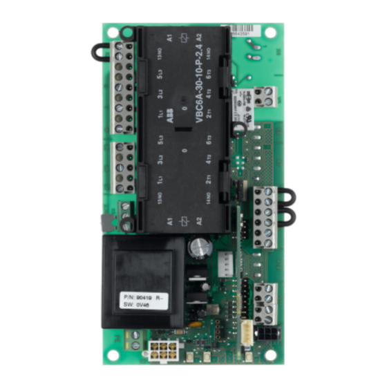
− CS 110 control unit with CSI buttons Low-voltage electricity − CS 110 control unit with LCD display board CS 250 / 110 − EN 60335-1 (Household and similar electrical appliances - Safety) −... - Page 5 Radio terminal block X18: Terminal block for buttons on housing X19: Terminal block for additional F1 = 250 mA shut-off system X21: AVE RS485 Relay Reversing contactor 250 mA fuse CS 110 Door Controls / Rev. A 05 – 5...
-
Page 6: Initial Operation
− The command and safety devices are installed and 230 V 400 V function properly. − The control unit housing with the CS 110 control unit is installed. 400V 3~/PE 230V 3~/PE NOTICE The door, the MFZ geared motor and the command and... - Page 7 AVE connector, which means that a bridge must be inserted at X2:1/2. 1-phase operator a = Thermo switch b = Emergency release / emergency hand chain / emergency hand crank OPEN CLOSE CS 110 Door Controls / Rev. A 05 – 7...
- Page 8 If no emergency stop is connected, the input must be 7: RS 485 A bridged. 8: Safety circuit output 9: 12V NOTICE If no limit switch is connected at RS885, then the safety circuit (4/8) must be bridged. 8 – CS 110 Door Controls / Rev. A 05...
- Page 9 External key switch CS 3-button input unit STOP OPEN CLOSE STOP OPEN CLOSE NOTICE If no stop system is connected at X9, then the input must be bridged. Connection for relay output CS 110 Door Controls / Rev. A 05 – 9...
- Page 10 J2 Mode of operation for opening direction: Open: deadman mode Closed: press-and-release NOTICE Operation with the press-and-release mode is allowed only if the safety devices required by the regulations are in place. 10 – CS 110 Door Controls / Rev. A 05...
-
Page 11: Initialisation
Press the + and - buttons on the circuit board at the same time and hold pressed for 5 seconds. The red LED will flash rapidly. Alternatively, two of the phases of the door operator can be swapped with each other. CS 110 Door Controls / Rev. A 05 – 11... - Page 12 Press the “P” button to leave adjustment mode. NOTICE − The adjustment mode will not end automatically. In order to return to normal operating mode, you must leave adjustment mode by pressing the “P” button. 12 – CS 110 Door Controls / Rev. A 05...
-
Page 13: Programming Using The Lcd Monitor
− Displays the status of the function DIAGNOSTICS If the Jumper H is pulled out, the “+”, “-” and “P” buttons will have no effect. The display will continue to function. CS 110 Door Controls / Rev. A 05 – 13... -
Page 14: Navigator (Only With The Lcd Monitor)
10. Navigator (only with the LCD monitor) 14 – CS 110 Door Controls / Rev. A 05... -
Page 15: Input Mode (Lcd Monitor)
MOD 1: AVE MOD1, MOD2 MOD2 SWITCH MOD 2: mechanical limit switches NOTICE The parameters FINE CLOSE, FINE OPEN and ROT.FIELD can be used only in conjunction with the AVE limit switch. CS 110 Door Controls / Rev. A 05 – 15... -
Page 16: Error Indication And Elimination
System stopped. Acknowledge the error by pressing Stop; restart is possible by pressing button. NOTICE After the cause of the error has been remedied, the control unit must be disconnected from the power supply and then recon- nected. 16 – CS 110 Door Controls / Rev. A 05... -
Page 17: Door Cycle Counter
In storage: -25 °C ... +70 °C Air humidity: Up to 80% with no condensation Vibration: Low-vibration mounting, e.g. on a masonry wall Protection class IP 65 Weight Approx. 1.8 kg CS 110 Door Controls / Rev. A 05 – 17... -
Page 18: Ec Declaration Of Incorporation
- Emission standard for residential, commercial and light-industrial environments EN 60335-1 Household and similar electrical appliances - Safety EN 60335-2-103 Particular requirements for drives for gates, doors and win- dows 18 – CS 110 Door Controls / Rev. A 05... - Page 19 CS 110 Door Controls / Rev. A 05 – 19...
- Page 20 #1700012038 #103730...
Need help?
Do you have a question about the CS 110 and is the answer not in the manual?
Questions and answers