Table of Contents
Advertisement
Quick Links
Advertisement
Table of Contents
Troubleshooting

Related Manuals for Huvitz CLM-4000


Summary of Contents for Huvitz CLM-4000
- Page 2 ------------------------------------------------------------------------- CLM-4000 User Guide Operator Manual Auto Lensmeter CLM-4000...
- Page 3 HUVITZ reserves the right to make changes in its products or product specifications at any time and without prior notice, and is not required to update this documentation to reflect such changes.
-
Page 4: Table Of Contents
------------------------------------------------------------------------- CLM-4000 User Guide CONTENTS INTRODUCTION....................... 6 1.1................... 6 UTLINE OF THE INSTRUMENT 1.2....................... 6 LASSIFICATION SAFETY INFORMATION ..................7 2.1......................7 NTRODUCTION 2.2....................8 AFETY YMBOLS 2.3................... 9 NVIRONMENT FACTORS 2.4................... 12 AFETY RECAUTIONS FEATURES ...................... - Page 5 CLM4000 User Guide -------------------------------------------------------------------------- 7.2....................23 SAGE OF BUTTONS DESCRIPTION OF SCREEN LAYOUT ..............26 8.1..................26 EASUREMENT CREEN 8.1.1. Detail explanation ..................27 8.2................29 BOUT THE PROGRESSIVE DISPLAY 8.2.1. Detail explanation ..................30 8.3. UV S ......................31 CREEN 8.3.1. Detail explanation ..................31 8.4.
- Page 6 ------------------------------------------------------------------------- CLM-4000 User Guide 9.4.2. Measuring at The Progressive Display............57 9.5..................58 ONTACT ENSES 9.6..................59 ONTACT ENSES 9.7. UV L ............... 61 RANSMISSION ATIO OF IGHT 9.8..............62 ARKING OCUS AND YLINDRICAL 9.8.1. When there is no astigmatism..............62 9.8.2.
-
Page 7: Introduction
Introduction 1.1. Outline of the instrument The Automatic Lensmeter CLM-4000 is the equipment for measuring the refractive power of lenses and gives the spherical, cylindrical and axis of the lenses. The Automatic Lensmeter CLM-4000 also contains the PD(=pupil distance) measurement and the UV Protection Ratio Test. The automatic lensmeter CLM- 4000 can measure both the uncutted singular lenses and the framed glasses. -
Page 8: Safety Information
------------------------------------------------------------------------- CLM-4000 User Guide Safety Information 2.1. Introduction Safety is everyone’s responsibility. The safe use of this equipment is largely dependent upon the installer, user, operator, and maintainer. It is imperative that personnel study and become familiar with this entire manual before attempting to install, use, clean, service or adjust this equipment and any associated accessories. -
Page 9: Safety Symbols
CLM4000 User Guide -------------------------------------------------------------------------- 2.2. Safety Symbols The International Electrotechnical Commission (IEC) has established a set of symbols for medical electronic equipment which classify a connection or warn of any potential hazards. The classifications and symbols are shown below. Save these instructions I and O on power switch represent ON and OFF respectively. -
Page 10: Environment Factors
------------------------------------------------------------------------- CLM-4000 User Guide Extra Symbols External serial communication port. User can transmit the memorized data to other equipment such as Huvitz’s other machines or PC. 2.3. Environment factors Avoid the following environments for operation or storage: Where the equipment is exposed to water vapor. - Page 11 CLM4000 User Guide -------------------------------------------------------------------------- Where the equipment is exposed to direct sunlight. Where it is near the heat equipment. Don’t disassemble the product or open. We aren’t responsible for it for nothing. Don’t plug the AC power cord into the outlet Before the connection between devices of the equipment is completed.
- Page 12 ------------------------------------------------------------------------- CLM-4000 User Guide Pull out the power cord with holding the plug, not the cord. Avoid places where the ambient temperature falls below 10℃ or exceeds 40℃ for normal operation, or below -5℃ or exceeds 50℃ (14℉-104℉) for transportation and storage.
-
Page 13: Safety Precautions
The equipment must be operated only by, or under direct supervision a properly trained and qualified person. Modifications of this equipment may only be carried out by Huvitz’s service technicians or other authorized persons. Customer maintenance of this equipment may only be performed as stated in the User’s Manual and Service Manual. - Page 14 This equipment may only be used together with accessories supplied by Huvitz’s. If the customer makes use of other accessories, use them only if their safe usability under technical safety aspects has been proved and confirmed by Huvitz or the manufacturer of the accessory.
-
Page 15: Features
CLM4000 User Guide -------------------------------------------------------------------------- likely to cause harmful interference. Independent power supply system is recommended. Features You can measure the center and refraction power of lenses with ease and rapidity. In case of framed lens, single/binocular PD can be measured automatically in addition to the refraction power of each lens. -
Page 16: Notes For Using The Instrument
------------------------------------------------------------------------- CLM-4000 User Guide Notes for using the instrument Do not hit or drop the instrument. The instrument may be damaged if it receives a strong impact. The impact can damage the function of this instrument. So handle with care. - Page 17 CLM4000 User Guide -------------------------------------------------------------------------- Don’t turn off the Display Protection Mode without an unavoidable reason. That’s why this instrument should perform the Display Protection function for the display protection as well as the compensation of temperature. Don’t place anything on the lens cap when you wake up this instrument from the display protection state.
-
Page 18: Configurations
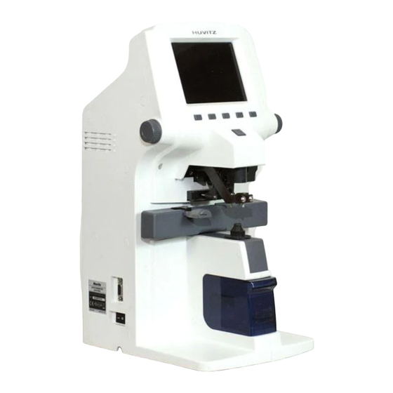
------------------------------------------------------------------------- CLM-4000 User Guide Configurations 5.1. Main Unit LCD Display LCD On/Off Lever Key Button Memory Button Brightness Lever Marker Lever Lens Holder Table Lever PD Sensor Lens Table Lens Supporter Printer Cover UV Cover [Figure 1. Component Names (I)] 1. - Page 19 CLM4000 User Guide -------------------------------------------------------------------------- Interface Connector Power Switch [Figure 2. Component Names (II)] Power Connector [Figure 3. Component Names (III)] 1. Interface Connector 2. Power Switch 3. Power Connector...
-
Page 20: Accessories
------------------------------------------------------------------------- CLM-4000 User Guide 5.2. Accessories (1) Printing Paper : Rolled paper for printing (2) Protection Cover : Polyvinyl cover for protection against dust (3) Soft Cloth for a Lens : A cloth for removing dust on a lens (4) Lens Support : General lens support (5) User’s Manual... -
Page 21: Settings And Preparation For Operating
CLM4000 User Guide -------------------------------------------------------------------------- Settings and Preparation for Operating 6.1. Receiving inspection Step 1. Checking accessories. Open the box and make sure that all the accessories (printing paper, protection cover, soft cloth for a lens, user’s manual) are in it Step 2. -
Page 22: Display Protection Function
------------------------------------------------------------------------- CLM-4000 User Guide And then turn on again. If the problem persists, please contact your local distributor or the manufacturer. Refer to the chapter ‘14. Service Infomation’. In summary, the testing procedures at start-up are as followings: Turn on the machine. Make sure that there is nothing on the lens cap. -
Page 23: Buttons For Operations
CLM4000 User Guide -------------------------------------------------------------------------- Buttons For Operations 7.1. Switching Screen According To the Button Selection Basic Display I Basic Display II UV Display Contact Lens Display User Setup Display Progressive Display [Figure 5. Switching Screen According To the Button Selection]... -
Page 24: Usage Of Buttons
------------------------------------------------------------------------- CLM-4000 User Guide 7.2. Usage of buttons MODE ① Select the basic display 1 or 2. ② If you press this button longer than 1 minute, Setup Screen will be shown. PROG Enter the Progressive Multi-Focal Screen. S→R In case of single lens, you can switch between left and right selection of the framed lens or you can select left /right lens. - Page 25 CLM4000 User Guide -------------------------------------------------------------------------- TRNS To transpose the sign of cylindrical reading. CNCT To go into the display for contact lens To Enter the UV Measurement Screen. D-SUN To measure the heavy dark sunglass lens. INFORMATION Especially the heavy dark sun-glass can’t be properly measured. In this case, press the ‘...
- Page 26 ------------------------------------------------------------------------- CLM-4000 User Guide To set the current state of transmission into 100%. To start recording the current data. STOP To stop recording the current data and to memorized the average value. MEM button To memorize the current measured-value.
-
Page 27: Description Of Screen Layout
CLM4000 User Guide -------------------------------------------------------------------------- Description of Screen Layout 8.1. Measurement Screen 2. Sequential No. 3. Lens Type 4. Active 1. Measured Data Direction 6. State icon 8. Total PD 7. Measuring point 5. Message Box [Figure 6. Screen Layout]... -
Page 28: Detail Explanation
------------------------------------------------------------------------- CLM-4000 User Guide 8.1.1. Detail explanation ① Measured Data Box for displaying the measured data. Each meaning of the content is as shown below. S : basic power C : cylinder power A : cylinder axis P : prism X, prism Y... - Page 29 CLM4000 User Guide -------------------------------------------------------------------------- ⑥ State Icon Represents that there is no lens inserted on the left-bottom of the screen. If you insert a lens, a figure will be shown, which illustrates lens on the lens support. INFORMATION The lens icon with a curved band represents the progressive lens inserted on the lens cap.
-
Page 30: About The Progressive Display
------------------------------------------------------------------------- CLM-4000 User Guide 8.2. About the progressive display 1. Maximum ADD 2. Horizontal Guide Line 3. Vertical Indicator for Near Focus 4. Chaos Height 5. Target for Far Vision 6. Measuring Point 7. Tolerant Height 8. Addition [Figure 7. The display for the progressive powered lens]... -
Page 31: Detail Explanation
CLM4000 User Guide -------------------------------------------------------------------------- 8.2.1. Detail explanation ① Maximum ADD The maximum additive value after detecting the far vision focus. ② Horizontal guide line This line is a guide for moving the cross marker while finding the near focus. ③ Vertical indicator for near focus This vertical bar graph describes how far the current measuring point is from the near focus. -
Page 32: Uv Screen
------------------------------------------------------------------------- CLM-4000 User Guide 8.3. UV Screen 2. Current Transmission Ratio 1. Left Transmission Ratio 3. Right Transmission Ratio 4. Transmission Height [Figure 8. UV Screen Layout] 8.3.1. Detail explanation ① Left transmission Ratio Shows the left-side stored value. ②... -
Page 33: Contact Lens Display
CLM4000 User Guide -------------------------------------------------------------------------- 8.4. Contact Lens Display 1. SPH Graph 2. CYL Graph 3. Start Record 4. Stop Record 5. Score Graph of Each Point [Figure 9. Contact Lens Display] 8.4.1. Detail explanation ① SPH Graph Shows the spherical readings continuously. - Page 34 ------------------------------------------------------------------------- CLM-4000 User Guide ② CYL Graph Show the cylindrical readings continuously. ③ Start Record Start recording the continuous measurement. ④ Stop Record Stop recording the continuous measurement, calculates the average value of all readings and then stores them. ⑤...
-
Page 35: Setup Screen
CLM4000 User Guide -------------------------------------------------------------------------- 8.5. Setup Screen MENU E X I T O F F A U T O L E N S D I S P L A Y P R O G R E S S I V E O N L Y P R O G R E S S I V E A U T... - Page 36 ------------------------------------------------------------------------- CLM-4000 User Guide DISPLAY - NORMAL : normal display PROGRESSIVE - OFF : turns off the progressive function. - AUTO : auto detection of progressive lens. - PROGRESSIVE ONLY : uses progressive function only. AUTO MEASURE - ON : turns on auto storing function.
- Page 37 CLM4000 User Guide -------------------------------------------------------------------------- (mm). CYLINDER - MIX : displays the cylinder value with (+) sign when the power has (+) value and with (-) sign when the power has (-) value : always displays the cylinder value with (+) sign. : always displays the cylinder value with (-) sign.
- Page 38 ------------------------------------------------------------------------- CLM-4000 User Guide RS-232C Selects the protocol of RS-232C - OFF : turns off the external communication - LMTORK : turns on the protocol between CLM Model and MRK, CDR series. - LMTORK(2) : turns on the bilateral protocol between CLM Model and MRK, CDR series.
- Page 39 CLM4000 User Guide -------------------------------------------------------------------------- INFORMATION If you take out the test lens from the lens cap after finishing the measurement, the measured data is automatically printed out. INFORMATION Using ‘AUTO MEASURE’, ‘AUTO PRINTER’, ‘RS-232C’, and ‘PRINTER’, you can achieve the full automatic measurement. NAME You can input the company name here.
- Page 40 ------------------------------------------------------------------------- CLM-4000 User Guide - OFF : turns off the UV function. To turn ON/OFF the UV function. TIME To configure date and time. INFORMATION Select the input position by the left two buttons and increase/decrease the number by the third and the forth button. Pressing the Enter Key at the EXIT causes escape without saving and pressing the Enter Key at the End yields saving the changes.
- Page 41 CLM4000 User Guide -------------------------------------------------------------------------- - MIRAELOGO MODE : display as the MIRAELOGO MODE, which is the one of customized displaying. CONTACT REC - MANUAL REC : stop the continuous measurement by pressing [STOP] button by user. - AUTO REC : measure for the specified second and then stop automatically.
-
Page 42: Printout Format
------------------------------------------------------------------------- CLM-4000 User Guide 8.6. Printout Format Printout format is as follows [Figure 11. Printout Format of Framed Glass]... -
Page 43: Measurements
CLM4000 User Guide -------------------------------------------------------------------------- Measurements 9.1. Normal lenses [Figure 12. How To Measure a Normal Lens] Step 1 Press ‘CLEAR’ button( ) to initialize the state of measurement. The symbol ‘S’ must appear on the upper-right part of the screen. Step 2 Place the lens on the support and lower the lens holder. - Page 44 ------------------------------------------------------------------------- CLM-4000 User Guide OFF Center Alignment OK Marking OK [Figure 13. Order for Focusing] Step 4 If the lens has astigmatism power, turn the lens so that the astigmatism angle become 180°.
- Page 45 CLM4000 User Guide -------------------------------------------------------------------------- INFORMATION You don’t have to control astigmatism power to 180°if there is no astigmatism power or you have no plan to mark astigmatism focus and cylindrical axis. Step 5 Press ‘MEM’ button to store the measured data. If the memorizing function is working, outer box enclosing data will be thicker and the data will be fixed.
- Page 46 ------------------------------------------------------------------------- CLM-4000 User Guide INFORMATION When there is no lens, you will see the figure on the left-bottom of the screen displaying lens support with no lens. If the figure displays lens support with lens but there is no one actually, consult your agent. It might be mechanic disorder or distortion.
-
Page 47: Framed Lenses
CLM4000 User Guide -------------------------------------------------------------------------- 9.2. Framed lenses [Figure 15. Measurement of Framed Lens] Step 1 Press the ‘S->R’ button( ) to enter the measuring framed lens environment. Then, ‘L’ and ‘R’ will be shown on the upper-left and upper- right of the screen. - Page 48 ------------------------------------------------------------------------- CLM-4000 User Guide CAUTION The current measuring lens is the side of which background is highlighted with cyan color between the ‘ L ’ and ‘ R ’. Step 2 Place the right lens on the support and lower the lens holder.
- Page 49 CLM4000 User Guide -------------------------------------------------------------------------- INFORMATION If you don’t want the PD value, you can use the lens table and the horizontal support without using the PD location sensor. In this case, completely turn the PD location sensor out from the hooker. Otherwise, it can result in the interference between the PD location sensor and the lens.
-
Page 50: Progressive Multi-Focal Lenses
------------------------------------------------------------------------- CLM-4000 User Guide 9.3. Progressive Multi-Focal Lenses 9.3.1. The structure of progressive powered lens The Uncut Lens [Figure 16. The structure of single lens] INFORMATION The lens should be placed with its horizontal marks parallel to the lens table. - Page 51 CLM4000 User Guide -------------------------------------------------------------------------- The Mounted Lens 2~3mm 2~3mm [Figure 17. The structure of the typical progressive frame lens] INFORMATION The dimension of progressive powered lens depends on the specification of manufacture. INFORMATION The old type progressive lens may not observe the 2~3mm shift toward the frame center.
-
Page 52: Judging Progressive Lens
------------------------------------------------------------------------- CLM-4000 User Guide 9.3.2. Judging progressive lens Step 1 Make sure that the icon in the left bottom of display is in the standard mode as picture. Step 2 Place the lens over the lens cap and wait 2~3 seconds. -
Page 53: Measuring A Progressive Lens For Far Vision Power
CLM4000 User Guide -------------------------------------------------------------------------- INFORMATION Automatic Detection may not be available in case the progressive power is less than 1D. If so, press ‘ PROG ’ button( ) for progressive measurement. INFORMATION If the lens is not properly placed in Step 2, the normal lens icon (as picture) will be displayed in Step 3. -
Page 54: Measuring A Progressive Lens For Near Vision Power
------------------------------------------------------------------------- CLM-4000 User Guide INFORMATION Automatic detection may not be available if the progress area is expanded into the far vision focus. In this case placed the cross marker (+) at the close point to the center and press “ MEM ” button to set the focus of far vision. - Page 55 CLM4000 User Guide -------------------------------------------------------------------------- INFORMATION Make sure the horizontal indicator for near focus is located within the range of tolerance (No. 2 of figure 7.). INFORMATION In case the horizontal indicator is out of the tolerance range, move the right lens to right (left lens to left), since the near focus is located at 2~3mm toward the center of frame.
-
Page 56: Troubleshooting For Progressive Measurement
------------------------------------------------------------------------- CLM-4000 User Guide Case I Case II [Figure 20. The small framed lens] INFORMATION The old type progressive lens may not observe the 2~3mm shift toward the frame center. 9.3.5. Troubleshooting for progressive measurement ① Do not detect the progressive lens automatically Cause 1 : Lens holder is not located in the progressive area (Normal lens icon will be displayed in the left bottom of display.) - Page 57 CLM4000 User Guide -------------------------------------------------------------------------- ③ Difficult to detect the far vision focus Cause 1 : The progressive area is expanded into the far vision focus Solution : Place the cross marker(+) at the close point to the center and press "MEM"...
-
Page 58: General Multi-Focal Lenses
------------------------------------------------------------------------- CLM-4000 User Guide 9.4. General Multi-focal Lenses 9.4.1. Measuring at The Normal Display Step 1 Press the ‘ MEM ’ button after placing the lens over the first focus. Step 2 Press the ‘ MEM ’ button after placing the lens over the second focus. The first ‘ADD’... -
Page 59: Hard Contact Lenses
CLM4000 User Guide -------------------------------------------------------------------------- Step 4 If you want to check one more additional power, after moving the lens over the third focus area, press the ‘ADD2’ button( ). At that time, the measurement is done automatically. INFORMATION At every step, in case that automatic measurement isn’t done or you want a manual decision, please press the ‘... -
Page 60: Soft Contact Lenses
------------------------------------------------------------------------- CLM-4000 User Guide 9.6. Soft Contact Lenses We have to prepare the mechanical jig for measuring a soft contact lens. The procedures to measure a soft contact lens are as followings : Step 1 Select the ‘SOFT CONTACT’ after choosing the ‘LENS’ item in the setup screen. - Page 61 CLM4000 User Guide -------------------------------------------------------------------------- INFORMATION You can specify the measurement duration at the User Setup Page. And then if you turn on the ‘AUTO REC’ function, it is unnecessary for you to press ‘STOP RECORD’ button( ) to stop the continuous measurement. It stops automatically after the specified seconds.
-
Page 62: Transmission Ratio Of Uv Light
------------------------------------------------------------------------- CLM-4000 User Guide 9.7. Transmission Ratio of UV Light [Figure 21. How To Measure Transmission Ratio of UV Light] Step 1 Enter the UV Measurement Screen to press the ‘MODE’ button( and the ‘UV’ button( ) continuously. -
Page 63: Marking Focus And Cylindrical Axis
CLM4000 User Guide -------------------------------------------------------------------------- Step 2 Pull and extract the UV cover. Step 3 Press the ‘CAL’ button( ) to calibrate the transmission ratio into 100% if it is not. Step 4 Place the lens on the UV detector. Step 5 Press the ‘MEM’ button to memorize the transmission ratio and press the ‘PRINT’... -
Page 64: When There Is Astigmatism
------------------------------------------------------------------------- CLM-4000 User Guide [Figure 22. How To Mark Focus and Cylindrical Axis] 9.8.2. When there is astigmatism Step 1 Place the lens and control the lens so that it becomes ‘MARKING OK’. Step 2 Keep ‘MARKING OK’ and control lens up to the angle of prescription slip. -
Page 65: Prism
CLM4000 User Guide -------------------------------------------------------------------------- 9.9. Prism Step 1 Change the display format as the form (X-Y, P-B, mm) in the prescription slip. You can do this on the setup screen. Step 2 Control the lens so that the display value on the screen coincides with the prescribed prism value. -
Page 66: Maintenance
------------------------------------------------------------------------- CLM-4000 User Guide 10. Maintenance 10.1. Replacing Printing Paper [Figure 23. How to Replace the Printing Paper] Step 1 Open the printer cover. Step 2 Insert the paper into the printer shaft and put the shaft into the pre-defined position. -
Page 67: Replacing Fuse
CLM4000 User Guide -------------------------------------------------------------------------- Step 4 Lower the printer lever and turn the feeding velvet to roll the paper. Step 5 Close the printer cover. Step 6 Advance the paper out of the printer cover. INFORMATION Use a thermal printing paper of the width 57mm and the diameter of roll 50mm. - Page 68 ------------------------------------------------------------------------- CLM-4000 User Guide Step 1 Pull out the fuse box. Step 2 Replace the old one with the new one. Step 3 Put into the fuse box with the new one. INFORMATION Use 250V, T3.15AL fuse for the Auto Lensmeter CLM-4000.
-
Page 69: Retouching Ink
CLM4000 User Guide -------------------------------------------------------------------------- 10.3. Retouching Ink Take out the ink pad assembly like Figure 25. And then disassemble it and pour ink on the pad like figure 26. [Figure 25. Taking out the ink assembly] [Figure 26. Retouching ink ]... -
Page 70: Storage
------------------------------------------------------------------------- CLM-4000 User Guide 10.4. Storage During night time, be sure to cover the dust cover as the below picture, because some dust might make spoil your equipment. [Figure 27. Storage for night time] If you don’t use your equipment for one week or more, make sure that the dust cap should be fitted into the lens cap as the below picture. -
Page 71: Disposal
CLM4000 User Guide -------------------------------------------------------------------------- 10.5. Disposal NOTE To dispose the instrument, accessories, and components, follow local governing ordinances and recycling plans regarding disposal or recycling of instrument or device components. Especially a lithium battery may pollute the environment if the instrument or a lithium battery is abandoned. -
Page 72: Troubleshooting
------------------------------------------------------------------------- CLM-4000 User Guide 11. Troubleshooting 11.1. Various Messages Message box shows information when you are measuring or this instrument is out of order. Here is the description on messages that appear in measuring. ALIGNMENT OK : When the optic center falls within 0.5 prism. -
Page 73: How To Clean Pin Hole
Never use liquids such as alcohol, acetone, etc. Because such liquids might melt the glue on the 4-pin hole. After that, if the message “Check the lens cap and restart” isn’t be disappeared, please ask to your local distributor or the Huvitz service department. -
Page 74: Specifications
------------------------------------------------------------------------- CLM-4000 User Guide 12. Specifications Specification Table Measurement Range Sphere Power -25D ~ +20D Cylinder Power 0 to ±10.00D Cylinder Axis – 180 degrees(1 Step) Add Power 0 to +10D Prism Power 0 to 10Δ Precision Diopter Steps 0.01 / 0.125 / 0.25D Prism Power 0.01 / 0.125 / 0.25Δ... - Page 75 CLM4000 User Guide -------------------------------------------------------------------------- Abbe Values Manual Compensation Wavelength e-Line, d-Line LCD STN Color Display Display (320X240 LCD Backlight) Data Output RS-232C, Printer 9600,19200,38400,57600,115200 248 x 277 x 446 mm Dimensions 9.76 in. x 10.90 in. x 17.56 in. Weight Power Supply AC 100 - 240 V, 50~60Hz, 0.5A...
-
Page 76: Components List
------------------------------------------------------------------------- CLM-4000 User Guide 13. Components List Main Body Printing Paper Power Cord Lens Support Protection Cover Soft Cloth for Lenses Tweezers for Soft Lens pad Mechanical Jig for contact lens(Optional) Dust cap User’s Manual Ink for marking Protection Pad Kit from Scratches... -
Page 77: Service Information
CLM4000 User Guide -------------------------------------------------------------------------- 14. Service Information How to contact service: If there are any problems with the equipment, please follow the steps below: First of all, refer to the 10. Maintenance and 11. Troubleshooting sections according to the problem that you are encountered. And then follow the suggested sequences. - Page 78 ------------------------------------------------------------------------- CLM-4000 User Guide If you can’t contact with your local distributor, you can directly get in touch with the service department of the HUVITZ using the phone number and the address written in the below table. How to Contact HUVITZ Co., Ltd...
Need help?
Do you have a question about the CLM-4000 and is the answer not in the manual?
Questions and answers