Table of Contents
Advertisement
Advertisement
Table of Contents

Subscribe to Our Youtube Channel
Related Manuals for birddog NDI


Summary of Contents for birddog NDI
- Page 1 USER GUIDE...
-
Page 2: Table Of Contents
Function Key Assignment ..................19 Factory Default ......................19 Tally - GPI I/O ....................... 20 Password Setting ......................20 Joystick Zoom Setting ....................21 Model Info ........................21 Adding an NDI® Camera to the Keyboard ..........22 Adding Cameras Manually ..................22... - Page 3 Adding non-NDI® Cameras to the Keyboard ........23 Adding a VISCA over IP Camera to PTZ Keyboard .........23 Interacting with Cameras ................26 Controlling Cameras ....................26 NDI® Keyboard Router ....................27 Setting and calling presets................28 Creating Presets ......................28 Calling Presets ......................
- Page 4 Copyright Copyright 2021 BirdDog Australia all rights reserved. No part of this manual may be copied, reproduced, translated, or distributed in any form or by any means without prior consent in writing from our company. Trademark Acknowledgement and other BirdDog trademarks and logos are the property of BirdDog Australia. Other trademarks, company names and product names contained in this manual are the property of their respective owners.
- Page 5 • This device must accept any interference received, including interference that may cause • undesired operation. LVD/EMC Directive This product complies with the European Low Voltage Directive 2006/95/EC and EMC Directive 2004/108/EC. NDI® is a registered trademark of NewTek, Inc.
-
Page 6: Welcome To Birddog
Your PTZ Keyboard is a powerful and sophisticated device, so please read this manual before use and retain for future reference. If you are new to the world of NDI® or BirdDog PTZ Keyboard, begin with Getting Started With Your Keyboard. -
Page 7: Ptz Keyboard Overview
BirdDog PTZ Keyboard is a full featured and versatile PTZ keyboard that supports NDI®, NDI®|HX, Visca over IP, RS422, and RS232. By harnessing BirdDog’s next generation NDI® and IP technology, it’s never been easier to discover, connect, and control your PTZ cameras. - Page 8 NDI® stream and piped where required on your network and converted back only at the neccessary endpoints. BirdDog has been on the NDI® journey since the very beginning and your PTZ Keyboard is just one of our products designed to take advantage of the features and potential of NDI®.
-
Page 9: What's In The Box
What’s in the box? 1x BirdDog PTZ Keyboard 1x Power Adaptor & Power Cord 1x Junction box 1x RJ45 Control Cable 1x Tally light Terminal Contact Optional Accessories 1x RJ45 to Phoenix Breakout 1x RJ45 Coupler 1x RS232 8 Pin Mini Din to Phoenix... -
Page 10: Getting Started With Your Ptz Keyboard
Getting Started With Your PTZ Keyboard If you are new to the world of NDI® or BirdDog cameras, please follow this quick start guide to become familar with the basic setup of your new camera. Your PTZ Keyboard at a Glance If you are new to PTZ Keyboard, it may be helpful to visualize the layout as follows. -
Page 11: Connections
Connections BirdDog products default to DHCP, so for the purposes of this quick start guide, we’ll assume: You are also using a managed DHCP IP configuration on your network. You have connected NDI® cameras, such as the BirdDog P200. Power You’ll have to decide how you are going to power your PTZ Keyboard. - Page 12 Press the SEARCH button to display the SEARCH menu. Select NDI-IP as the Protocol. Click the P/T Speed dial. Select YES to start the search by once again clicking the P/T Speed dial. A list of discovered cameras will be displayed. Scroll through the cameras using the Zoom Speed dial.
-
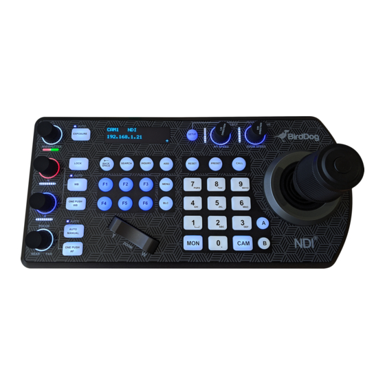
Page 13: Keyboard Main Panel
Keyboard Main Panel White Balance, (Auto, Manual) Press once for Auto. • • Press again to activate manual adjustments. Lock Locks all image adjustment buttons and dials. Exposure (Auto, Iris PRI, Shutter PRI) IP Interface Buttons For interacting with IP cameras. LCD Screen For navigating PTZ Keyboard settings. - Page 14 Pan Tilt Speed knob Rotate: Speed adjustment / Navigate (in menu). • Press: Select (in menu). • Long press (3 sec): Invert L/R direction. • Call For calling camera presets. Zoom Speed knob • Rotate: Zoom speed adjustment / adjust value (in menu). •...
-
Page 15: Keyboard Rear Panel
Kensington Security Slot Use a lock to physically secure the keyboard in place. Audio Port For headset use when PTZ Keyboard is added to a BirdDog Comms group. Tally / Contact (GPI I/O Connector) Tally control interface. RS232 Interface / RJ-45 Port Connect RS232 adapter. -
Page 16: Keyboard Screen
Keyboard Screen Camera identifier Identifies the camera being controlled. Protocol Baud Rate Communication Status Indicator (for the current device) Network connectivity Indicator “+” displayed means that the network is successfully connected. “+” not displayed means that the network is not connected. Tilt Reversal Indicator Pan Reversal Indicator IP Address (of the currently controlled camera) -
Page 17: Junction Box
Junction Box RJ45 Port For connection between Junction Box and The Keyboard Controller 12V DC Power Port Connect the supplied DC power adaptor and cord. Junction Box body Terminal Contact Connection For RS422 or RS232 use. RJ45 Port For connection between Junction Box and the camera. Use a network cable to connect directly. NOTE: Do not use the top row of holes, as these are not contact ports. -
Page 18: Powering Ptz Keyboard
Powering PTZ Keyboard Power the keyboard using one of the following options: Power Supply (included) • Power voltage tolerance = 5V - 48V. 12V DC • The keyboard can be powered with at Power Adaptor least 5VDC. This allows for longer power runs between the power source and the keyboard. -
Page 19: Connecting Ptz Keyboard To Your Network
If using PoE+, you can use a single Ethernet cable to connect the Keyboard’s IP port to a port on an Ethernet switch. This allows you to use NDI® for control as well as using the web interface for set up of PTZ Keyboard. -
Page 20: Navigating The Menus
Navigating the Menus Press the SETUP button to display the SETUP menu on the LCD screen (Default Password: 0000). The password can be changed at: SETUP > KEYBOARD SETTING > PASSWORD SETTING. The following controls are used to navigate the menus and select/save parameter values. Use the P/T Speed dial to navigate the menus and the Zoom Speed dial to change and save your settings. -
Page 21: Button Light
IP Configuration The IP address can be set to either STATIC or DHCP (default). DHCP Move the cursor to the TYPE field, and rotate the Zoom Speed dial to change the value to DHCP. Click the Zoom Speed dial to save. STATIC If setting the IP address to a STATIC address, ensure that the Type field displays STATIC, and then rotate the P/T Speed dial to move the cursor between the IP address octets. -
Page 22: Function Key Assignment
Function Key Assignment Keys can be configured as shortcuts to activate camera functions. From the Keyboard Setup menu, move the cursor to the ASSIGNED KEY field. Rotate the Zoom Speed dial to select the key to configure. Click the P/T Speed dial to apply the function to the assigned key. Keys can be assigned to the following camera features: Home: Command the selected camera to activate its ‘Home’... -
Page 23: Tally - Gpi I/O
Tally - GPI I/O To configure the Tally settings. Command Select STANDARD: Sets the input/output method to Standard method. The camera numbers and input/output pin numbers have a 1:1 correspondence. If the unit and cameras are • connected by serial connection, cameras 1 to 7 correspond to input/ outputs 1 to 7. -
Page 24: Joystick Zoom Setting
Joystick Zoom Setting Change this setting to ON if you wish to use the joystick to control the camera’s zoom. This setting can be changed by rotating the Zoom Speed knob while the setting is selected. Click the Zoom Speed knob to save this setting if changed. •... -
Page 25: Adding An Ndi® Camera To The Keyboard
Repeat this process for each discovered camera that you wish to add to the PTZ Keyboard. Adding Cameras Manually Navigate to the Protocol setting and select NDI. Click the P/T Speed dial to display the NDI Camera Setup menu.. CAMERA SETTING MENU NDI CAMERA SETUP MENU... -
Page 26: Adding Non-Ndi® Cameras To The Keyboard
Adding non-NDI® Cameras to the Keyboard Manually adding cameras The keyboard can store settings to control up to: 255 cameras by RS485 PELCO protocol separately. • 7 cameras by VISCA via RS422 group A separately. • 7 cameras by VISCA via RS422 group B separately. - Page 27 Rotate the P/T Speed dial to move the cursor between the IP address octets. Move the cursor to each octet and use the alphanumeric keypad to enter its value. Rotate the P/T Speed dial to move to the next octet and repeat until all IP address octets are set to the desired values. Click the Zoom Speed dial to save.
- Page 28 Adding VISCA over IP Cameras Under WAN Control Make the following changes at the camera and PTZ Keyboard. At the Camera Location: INTERNET For commands to flow from outside the network in to a camera, ports must be opened. Contact the network administrator at the camera location to create a port-forwarding rule in the router allowing commands...
-
Page 29: Interacting With Cameras
Interacting with Cameras Options for Calling a Camera Use the keypad to call the camera by CAM ID. Enter the CAM ID on the keypad. Press CAM. Call the IP cameras by selecting from a list of available devices. Press the INQUIRY button. Select a protocol. -
Page 30: Ndi® Keyboard Router
To do this, select KB_ROUTER as the output channel of the desired NDI® sources. Now, selecting Cam 1 on the keyboard will display the Cam 1 NDI® stream, and then se- lecting Cam 2 on the keyboard will display the Cam 2 NDI® stream. Importantly, this output... -
Page 31: Setting And Calling Presets
Setting and calling presets. Creating Presets HOLD 3 SEC. Move the camera to the desired position. Enter the desired preset number on the alphanumeric keyboard, and then hold the PRESET button for 3 seconds to save. Calling Presets PRESS Enter the preset number on the alphanumeric keypad. Press the CALL button. -
Page 32: Dual Rs422 Button A/B
Dual RS422 Button A/B There are 2 RS422 ports on the back panel of the Keyboard. Up to 7 cameras can be daisy chained from each RS422 port. You can toggle between these by using the A and B buttons. Adjusting Image Parameters The following image parameters can be set/adjusted by using the Image Adjustment Panel. -
Page 33: Web User Interface Configuration Panel
• Allows you to remotely soft reboot the device, for example, after installing new firmware. Restart the video processing engine • Useful for ensuring that the NDI® video engine will process as per any manual settings you may have made. -
Page 34: Network
In order to access the web configuration panel on a network which is configured to a different subnet, change your computers IP address to match the BirdDog unit. Once you gain access to the BirdDog Dashboard panel, choose your IP address to match the rest of the devices on your network. -
Page 35: System
You can name each PTZ Keyboard with a name that makes sense for each production. This name will appear on any NDI® receiver over the network. This name will appear on any NDI® receiver over the network. Click in the BirdDog Name field to edit the name. The name must not include any special characters and can be any combination of a-z (lower case only), 1-0, and ‘–‘. - Page 36 Firmware Updates NDI Network Settings If you choose to use a NDI® discovery server, you can configure it in this tab. By default, NDI® utilizes mDNS (multicast Domain Name System) to create the zero configuration environment for discovery. The primary benefits of using mDNS is that it requires little or no administration to set up. Unless the network is specifically configured to not allow mDNS, NDI®...
- Page 37 API mode. In API mode, you can program custom commands to control network devices. API Settings RESTful API commands are available to all BirdDog hardware devices, allowing users to remotely interact with devices. In this tab, you can configure commands that can be saved to PTZ Keyboard Function Keys when in API mode.
- Page 38 Target device and command: http://x.x.x.x:8080/birddogpic2setup Parameter and value: {“pic2_camstabilizer”: “cstboff”} Example 2 In the example below, the F3 key is configured to instruct a BirdDog device, identified by address ‘x.x.x.x’, to connect to a specific NDI® source ”birddog (stream1)”. Target device and command: http://x.x.x.x:8080/connectTo...
- Page 39 Remote IP List By default, NDI® devices are visible to each other only when they’re on the same VLAN. If you want visibility or control of a device on a different VLAN, you need to add it’s address manually as a Remote Click the CHOOSE FILE button to load your Remote IP List in JavaScript Object Notation (JSON) format.
-
Page 40: Using Other Control Protocols
Using Other Control Protocols Use VISCA OVER IP Control IP Connection - Using VISCA OVER IP Control Protocol - with a Visca Over IP ready Camera. Video Switcher Tally/contact signal HDMI/SDI Remote control signal, Network Cable CAT5/6 with VISCA OVER IP Control... -
Page 41: Cross-Protocol Mix Control
Cross-Protocol Mix Control Using VISCA, PELCO, VISCA OVER IP, NDI® in one single system. - Page 42 PTZ Keyboard features cross protocol mix-control with RS232/RS422 and IP in one single system. VISCA RS422 Group A: 7 cameras VISCA RS232: 7 cameras VIsca over IP VISCA RS422 Group B: 7 cameras Pelco RS485: 255 cameras Up to Multiple Controllers, up to 255 cameras in a single network...
-
Page 43: Cross Protocol Mix Control
Cross Protocol Mix Control 12V DC Power Supply RS422 Camera(s) - A Ethernet Cables RS422 Camera(s) - B Serial Control Cables IP Cameras (VISCA over IP) Power Supply via Junction Box / PoE RS232 Camera(s) 12V DC Power Supply When the junction box is powered, it will provide power to the keyboard via any port that it is connected to i.e., RS232, IP, RS422(A), RS422(B). -
Page 44: Serial Port Connection
VISCA over IP, CGI*) in a single system. RS232 Connection Use for the controller with non-BirdDog camera connection. RS232 connection using network cable (follow T-568B standard pinout at keyboard end): 1 to 1 connection - Follow the pinout for the RS232 port on the keyboard to use CAT5/6 cable to make a cable suitable for controlling your camera. - Page 45 RS232 connection using multicore control cable. RS232 connection - Via Junction Box - Camera with RS232-Serial connector. RS232 connection with the camera having 8 Pin Mini Din RS232 connector. RS232 connection - Via Junction Box - Camera with 8 Pin MIni Din RS232 serial connector.
- Page 46 RS232 Daisy Chain Multiple Camera connection. RS Daisy Chain Connection - Via Junction Box - Camera with RS232 serial connector RS232 connection using RJ45 to Phoenix connector adaptor. RS232 Daisy Chain Connection - Using RJ45 to Phoenix connector adaptor (not included).
- Page 47 RS422 Connection Use for the controller with non-BirdDog camera connection. For BirdDog camera connection see the separate section following. Follow the diagram below for the following options: RS422 connection using network cable (follow T-568B standard pinout at keyboard end): 1 to 1 connection - Follow the pinout for the RS422 port on the keyboard to use CAT5/6 cable to make a cable suitable for controlling your camera.
- Page 48 RS422 connection using multicore control cable. RS422 Daisy Chain Multiple Cameras connection. RS422 Daisy Chain Connection - Via Junction Box - Camera with RS422 Serial Port.
- Page 49 RS422 1 to 1 connection using RJ45 to Phoenix connector adaptor (Not Included). RS422 Connection - Use RJ45-RS422 adapter - Camera with RS422 serial connector.
- Page 50 RS422 Daisy Chain connection using RJ45 to Phoenix connector adaptor (not included). RS422 Daisy Chain connection - Via RJ45 to RS422/232 Adaptor - Camera with RS422 Serial Port.
- Page 51 RS485 Connection Use for the controller with non-BirdDog camera connection. Follow the diagram below for the following options: RS485 connection using network cable (follow T-568B standard pinout at keyboard end): 1 to 1 connection - Follow the pinout for the RS485 port on the keyboard to use CAT5/6 cable to make a cable suitable for controlling your camera.
- Page 52 RS485 connection using multicore control cable. RS485 Connection - Via Junction Box - Camera with RS485 serial connector. RS422 (A/B) Toggle RS422 A or B 12V DC Power Adaptor Multicore control cable Camera with Serial Port RX+R X- TX+ TX- GND TX RX NC NC GND RS485 Daisy Chain Multiple Cameras connection.
- Page 53 RS485 Daisy Chain connection using RJ45 to Phoenix connector adaptor (Not included). RS485 Daisy Chain Connection - Via RJ45 to RS422 Adaptor - Camera with RS485 Serial Port.
-
Page 54: Tally Light Gpi I/O Connection
Tally Light GPI I/O Connection GPI Connection with RS422 VISCA Control Connection Tally Light GPI Connection. Video Switcher Tally/contact signal HDMI/SDI RS422 control signal GPI Connection with VISCA OVER IP Control Connection Video Switcher Tally/contact signal HDMI/SDI Remote control signal, Network Cable CAT5/6 with VISCA OVER IP Control... -
Page 55: Appendix
Appendix PTZ Keyboard Pinout DC 12V TALLY/CONTACT RS232 B-RS422-A USB 2.0 FOR FIRM WARE UPGRADE ONL Y TALLY/CONTACT RS232 RS422 (A/B) Pin No. Function Pin No. Function Color Pin No. Function Color Pin No. Function Color CAMERA1 Orange/White Orange/White Orange/White CAMERA2 Orange Orange... -
Page 56: Ptz Keyboard Physical Dimensions
PTZ Keyboard Dimensions Unit: mm 120.7mm 25.0 21.2 278.0 132.0... -
Page 57: Glossary
NDI® (Network Device Interface) is a standard allowing for transmission of video using standard LAN networking. NDI® comes in two flavours, NDI® and NDI®|HX. NDI® is a variable bit rate, I-Frame codec that reaches rates of around 140Mbps at 1080p60 and is visually lossless. NDI®|HX is a compressed,... - Page 58 PELCO PELCO is a camera control protocol used with PTZ cameras. See also VISCA. Power over Ethernet. Port A port is a communications channel for data transmission to and from a computer on a network. Each port is identified by a 16-bit number between 0 and 65535, with each process, application, or service using a specific port (or multiple ports) for data transmission.
- Page 59 WELCOME TO THE FUTURE. 4.5.203-LTS/2...
- Page 60 bird-dog.tv hello@bi rd-dog.tv...
Need help?
Do you have a question about the NDI and is the answer not in the manual?
Questions and answers