
Subscribe to Our Youtube Channel
Summary of Contents for WINDY NATION SunTura SOT-TRKS-NF
- Page 1 SunTura Solar Tracker Kit Manual Revision 1.0 WindyNation SUNTURA SOLAR TRACKER SOT-TRKS-NF User’s Manual Page 1 of 10 08/09/2012 WindyNation...
-
Page 2: Table Of Contents
SunTura Solar Tracker Kit Manual Revision 1.0 Table of Contents Introduction ..............................3 Limited Warranty ..........................3 Restrictions ............................3 Warranty Claims & Return Procedures ....................3 Disclaimer ............................4 Limitation of Liability ........................... 4 Product Overview ............................5 Features .............................. 5 Safety Precautions .......................... -
Page 3: Introduction
1.2 R ESTRICTIONS No warranty will apply if the Product (i) has been altered or modified except by Windy Nation; (ii) has not been installed, operated, repaired, or maintained in accordance with instructions supplied by Windy Nation; (iii) has been subjected to abnormal physical, thermal or electrical stress, misuse, negligence, or accident. If Windy Nation determines that the problem with the Product is not due to a manufacturing defect in Windy Nation’s workmanship or materials, or otherwise does not qualify for warranty repair, then the Customer will... -
Page 4: Disclaimer
Windy Nation’s property on the date Windy Nation ships the repaired Product or part back to the Customer. Windy Nation will use all reasonable efforts within thirty (30) days of receipt of the defective Product to repair or replace such Product. If a warranty claim is invalid for any reason, the Customer will be charged at Windy Nation’s then-current rates for services performed and will be charged for... -
Page 5: Product Overview
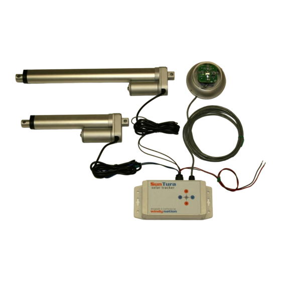
SunTura Solar Tracker Kit Manual Revision 1.0 2 PRODUCT OVERVIEW Building a complete solar tracking system has never been easier. The SunTura Solar Tracker Kit can be used directly on 12 volt or 24 volt systems. If you plan on using the SunTura Solar Tracker Kit on a grid tie system, we can supply you with a 12 volt power supply which can be plugged into the grid (110 AC or 220 AC). -
Page 6: North/South Linear Actuator Installation
SunTura Solar Tracker Kit Manual Revision 1.0 Additionally, there are four buttons on the top of the Electronics Box which allow one to manually move the linear actuators in the north, south, east and west directions. See Figure 2 below. Figure 2: Electronics Box manual controls and fuse locations. -
Page 7: East/West Linear Actuator Installation
SunTura Solar Tracker Kit Manual Revision 1.0 3.2.3 East/West Linear Actuator Installation The east/west linear actuator has a stroke length of 12 inches and also has two 5/16 inch diameter mounting holes. It is wired to the SunTura Tracking Electronics in the following manner: If the sun is located to the west of the solar tracker, the east/west linear actuator will extend so it positions the solar panels perpendicular to the sun’s light rays. -
Page 8: Fine Tuning The Led's For Optimal Solar Tracking
SunTura Solar Tracker Kit Manual Revision 1.0 Figure 5: Use Allen wrench to loosen set screws and remove Photo Sensor Dome with flat head screw driver. Next, mount the included screw sets into the three holes on the Photo Sensor. These screws can be used to mount the Photo Sensor to the solar tracker. - Page 9 SunTura Solar Tracker Kit Manual Revision 1.0 Figure 7: Bolt mounted perpendicular to solar panel angle. The LED’s on the Photo Sensor circuit board can be slightly adjusted to fine tune the accuracy of the solar tracking. The goal is to eliminate the shadow casted by the bolt in Figure 7. The LED’s can be moved slightly up or down to accomplish this task.
-
Page 10: Troubleshooting And Support
SunTura Solar Tracker Kit Manual Revision 1.0 4 TROUBLESHOOTING AND SUPPORT The SunTura Solar Tracker Kit is ruggedly constructed and requires minimal care. 4.1 C To clean your tracker, moisten a cloth with a few drops of mild hand dishwashing detergent in a cup of lukewarm water and gently wipe clean.
Need help?
Do you have a question about the SunTura SOT-TRKS-NF and is the answer not in the manual?
Questions and answers