Table of Contents
Advertisement
Advertisement
Table of Contents

Subscribe to Our Youtube Channel
Related Manuals for Wohler VIS 500


Summary of Contents for Wohler VIS 500
- Page 1 Manual Inspectioncamera Wöhler VIS 500 The measure of Technology...
-
Page 2: Table Of Contents
Contents Contents General information ......5 Operation Manual Information ....... 5 Copyright ............5 Notes ............. 5 Proper use ............. 5 Scope of supply ..........6 Storage and transport........6 Information on disposal ......... 7 Manufacturer ..........7 Important information ......8 Technical data ........ - Page 3 11.4.4 Settings ............33 Transmission of images via WLAN .. 36 12.1 Hotspot: VIS 500 WLAN network ....37 12.1.1 Change password and networkname ..38 12.1.2 Select WLAN channel if necessary ..... 40 12.1.3 Establishing a connection to a mobile device ..
- Page 4 Contents Declaration of Conformity ....53 Short Manual ........55 18.1 On/Off - Key Menu-Key ......55 18.2 Hidden menu ..........55 18.3 Menu on screen .......... 55 Points of sale and service ......57...
-
Page 5: General Information
General information General information Operation Manual Infor- This operation manual allows you to work safely with the Wohler VIS 500. Please keep this manual mation for your information. The Wohler VIS 500 should be employed by pro- fessionals for its intended use only. -
Page 6: Scope Of Supply
General information Scope of supply Device Scope of supply Wohler VIS 500 Monitor Service Camera Ø 1 ½ " pan and tilt color camera head, pluggable (option) Ø 1" miniature cam- era head, pluggable (option) Viper with 100 ft camera rod (65 ft. -
Page 7: Information On Disposal
General information Information on disposal Electronic equipment does not belong into domes- tic waste, but must be disposed in accordance with the applicable statutory provisions. You may hand in any defective batteries taken out of the unit to our company as well as to recycling places of public disposal systems or to selling points of new batteries or storage batteries. -
Page 8: Important Information
Important information Important information Body Protection WARNING! Never point a connected camera head at your own or somebody else's eyes when the monitor is switched on. The LEDs are extremely bright and can dazzle. WARNING! Guide the rod with due care and attention. As the rod is made of flexible material, it can make whip- ping movements if it slips. - Page 9 Important information Operating Temperature CAUTION! Do not use the camera in temperatures above 40°C. High temperatures can damage the camera. Resistance to water CAUTION! Only the camera head and the rod are waterproof Keep the camera system dry and protect it from water! Resistance to impacts CAUTION!
-
Page 10: Technical Data
Technical data Technical data Monitor Description Data Dimensions 0.8 x 0.5 x 0.2 ft Screen diagonal 7 inch Weight 710 g 7“ / 16:9 format TFT display 1024 x 600 pixel Fig. 1: Monitor Charging cable USB-C 5 V/3 A Power supply 3,7 V, 11400 mAh Li-Ion Akku... -
Page 11: Wöhler Pan & Tilt Camera Head (Optional)
Technical data Wöhler pan & tilt Description Data camera head (optional) 1/3“ Color CMOS Classification Type Resolution 720 x 576 px (PAL) 720 x 480 px (NTSC) Lens f = 2,3 mm, F = 2,5 Light source 12 white LEDs Protection Waterproof to IP 67 (up to 1 m depth for... -
Page 12: Mini Camera Head (Optional)
Technical data Mini camera head Description Data (optional) 1/3“ Color CMOS Classification Type Resolution 720 x 576 px (PAL) 720 x 480 px (NTSC) f = 0.09 “, F = 2.5 Lens Light source 12 white LEDs Protection Waterproof to IP 68 (up to 1181“... -
Page 13: Electronic Meter Counter
Technical data Electronic meter Description Data counter 0,9” Resolution Max. deviation 5 % of reading Storage Description Data Memory Internal storage or USB stick Resolution of savings Image, 1024 x 600 Pixel with text overlays (.png) Image, 1024 x 685 Pixel without text overlays (.png): Video (.mkv):... -
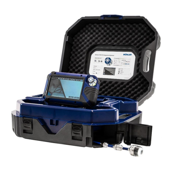
Page 14: Design And Function
Design and function Design and function Video Inspection System Fig. 6: Wöhler VIS 500 Camera System... - Page 15 Design and function Legend: Monitor Short Manual Space for accessories, charging cable, camera head etc. Opening for the camera head and camera rod (rod outlet) Lock of the camera case Locks of the lower shell...
-
Page 16: Monitor
Design and function Monitor Fig. 7: Monitor Fig. 8: Bottom side of the monitor with terminal strip... - Page 17 Design and function Legende: Fixing holes for glare protection Bottom side of the monitor with terminal strip Operation panel CTIA standard connection for headset with headphone and microphone to rec- ord a commentary during video recording USB port for stick Reset opening USB port for charging cable Notch for placing the monitor on the connecting rail of the case...
-
Page 18: Starting To Use Your Camera System
Starting to use your camera system Starting to use your camera system Activating the If the camera system cannot be switched on dur- ing initial operation, you have two options for acti- battery vating the battery: Connect the monitor to the mains via the power supply unit. - Page 19 Starting to use your camera system To put the monitor upright, grasp it by the up- per edge and tilt it up. To return the monitor to the transport position, fold it down. CAUTION! If there is any resistance when pushing down the monitor, check the connection cable has been placed under the monitor properly rolled up.
-
Page 20: Charging The Rechargeable Battery
Starting to use your camera system Proceed as follows to release the monitor from the holder: Put the monitor in an upright position. Press against the lever on the rear of the moni- tor. At the same time pull the monitor out of the holder. - Page 21 Starting to use your camera system the camera can only be switched on when it is connected to the mains. To charge the battery, connect the monitor to the mains using the USB power pack included in the scope of supply. ...
-
Page 22: Keys And Their Functions
Keys and their functions Keys and their functions Control pad Image key/ Confirmation On/Off key/ Video key/ Menu key Back key Fig. 16: Monitor keys On/Off key Switching on the system When the system is switched off, press and hold the ON/Off key for approx. -
Page 23: Video Key
Keys and their functions Video key NOTE! Before starting to record a video make sure the menu is not displayed. Otherwise it is not possible. To start recording a video, briefly press the video key. To stop recording the video, briefly press the video key again. -
Page 24: Image Key
Keys and their functions Image key NOTE! The camera will only capture an image when the menu is not displayed. Press the image key briefly to capture a photo. It is possible to capture an image while recording a video. -
Page 25: Display Elements When Menu Is Displayed
Display elements when menu is displayed Display elements when menu is displayed 10 11 Fig. 17: Display Legend: Brightness control Reset meter counter Image and video gallery System menu “Horizon” with tilt and pan angle display / Home function “Brightness” slider (the “Focus” slider can also be displayed here) Video recording time Meter counter USB Stick inserted... -
Page 26: Displayed Position Of The Camera Head
Displayed position of the camera head The horizon icon indicates the downward gradient Displayed posi- of the pipe. tion of the cam- Example: era head - 5° corresponds to a downward gradient of 5° (+ 5° corresponds to an upward gradient of 5°) Heaven Earth Fig. -
Page 27: Live Menu
Live menu Via the live menu, settings can be made on the ca- Live menu mera system. To display the menu, briefly tap the Menu key when the system is switched on. The following Icons appear: Brightness control, Reset meter counter, Image and video gallery, System menu. -
Page 28: Image And Video Gallery
Live menu 11.3 Image and video gallery Use the up/down arrows to go to the gallery icon and confirm with the confirmation key the right arrow. Leave the image and video gallery with the back key or the left arrow. Fig. - Page 29 Live menu icons are displayed in the upper left corner of the display. Go back to gallery with the back key or left ar- row. Select the files to be deleted. Delete images and videos With the up/down arrows go to “Function se- lection”...
- Page 30 Live menu How to see videos on a PC NOTE! During video playback, the date, time and meter count are always displayed in the video, regard- less of which media player is used. You can playback a video on the PC using the Windows Media Player or VLC Player once you have saved the respective video file to the PC.
-
Page 31: System Menu
Live menu 11.4 System menu Select the system menu. Fig. 28: System menu selected The System menu has the following submenus: WLAN, Locator, Settings, Info menu. The active fsubmenus are highlighted blue, inactive submenus are grey. Fig. 29: System menu with WLAN (1), Locator (2), settings (3) and Info menu (4) This function is described in the following chapter... -
Page 32: 11.4.2 Locator
Live menu In the submenu “Locator” you can activate and de- 11.4.2 Locator activate the „Locator transmitter“ inside the cam- era head. It is possible to select a transmission fre- quency. Fig. 31: Locator icon 11.4.3 Activate the locator Select the transmission frequency with the detection confirmation key... -
Page 33: 11.4.4 Settings
Live menu 11.4.4 Settings Display backlight Here the display backlight can be adjusted. (To adjust the illumination of the camera head, see chapter 11.1. When the camera is turned on, the display bright- ness is always set to 70%. It is possible to adjust the display brightness in 10 levels from 10% to 100%. - Page 34 Live menu Meter Count Unit The counted meters can be displayed in 2 units: 0.00 m (Meter) 0.00 ft. (feet) Activate the requestet unit with the Confirma- tion key or the right arrow. Fig. 34: Selection of unit of the counted meters Date/Time Here you can change the type of display of date...
- Page 35 Live menu Image overlays The photos taken with the Wöhler VIS 500 contain all the information shown in the camera display (comments, meter count etc.) Activate or deactivate the settings with the Confirmation key or the right arrow. The settings are saved automatically and are re- tained after switching the camera off and switching on again.
-
Page 36: Transmission Of Images Via Wlan
WLAN function of the camera system. This function allows you to view live images on the Fig. 40: WLAN icon VIS 500 monitor while a colleague, e.g. at the other end of the pipe, watches the videos live on his mo- bile device. -
Page 37: Hotspot: Vis 500 Wlan Network
Transmission of images via WLAN 12.1 Hotspot: VIS 500 WLAN network The Wöhler VIS 500 builds its own WLAN network if you select the WLAN mode “Hotspot“. It is possible to transmit image files to a mobile device. Select Hotspot > Start Hotspot. -
Page 38: Change Password And Networkname
Transmission of images via WLAN 12.1.1 Change password It is possible to change the network name and the password if necessary. When changing the net- and networkname work name, you could, for example, use your own company name as the network name. ... - Page 39 Transmission of images via WLAN Digits 0 to 9 The following special characters (network name): _ - ! # $ % & ' ( ) + , . / : ; < = > ? @ ^ ` { | } ~ The following special characters (password): _ - ! "...
-
Page 40: Select Wlan Channel If Necessary
Transmission of images via WLAN 12.1.2 Select WLAN If necessary, it is possible to select the WLAN channel. 13 WLAN channels can be selected channel if Default setting: chanel 1 necessary NOTE! Normally it is not necessary to select another WLAN channel. -
Page 41: Establishing A Connection To A Mobile Device
Internet. Therefore, the warning message "Internet not available" appears. Wait until the Wöhler VIS 500 establishes con- tact with your mobile device. You now have the possibility to view the live video in the Wöhler Videoinspection App on your mobile... -
Page 42: Wlan: Using An Existing Wlan Network
WLAN: Using an existing WLAN network In the “WLAN” mode, you dial into an existing net- work both with the Wöhler VIS 500 and with a mo- bile device or a WLAN-capable PC or Laptop. This way, live image transmission from the camera to the mobile device/laptop is even possible over a certain distance. - Page 43 Transmission of images via WLAN Select the same network that you dialed into with the camera. Enter the password of your network. You now have the possibility to view the live video in the Wöhler Videoinspection App on your mobile device.
-
Page 44: Faults
Faults Faults 13.1 Reset It is possible to rectify certain malfunctions by initi- ating a reset operation. The reset hole is located on the rear of the monitor next to the camera con- nection port, see Figure opposite. Reset 1: Insert a thin object, for example a Fig. -
Page 45: Maintenance
Maintenance Maintenance 14.1 Information on mainte- Proper operation of the Service Camera requires regular maintenance. The following maintenance nance works can be done by the user himself. 14.2 Replacing the dome of NOTE! the camera head The camera head is supplied protected by a plas- tic dome, which can be replaced if necessary, for example, if it becomes scratched. -
Page 46: Cleaning The Viper And The Rod
Maintenance 14.5 Cleaning the viper and The viper with the rod is placed in the lower shell of the case. It is possible to take it out and clean it the rod with water. In this case the camera head can re- main fixed to the camera rod. - Page 47 Maintenance Open the black locks of the lower shell. Pull the camera cable through the opening of the upper shell. Remove the viper from the case. Fig. 54: Lower shell opened Cleaning the viper and the rod CAUTION! Take care that no water comes into the plug con- nections of the rod.
- Page 48 Maintenance Clean the viper and the rod with water. Fig. 56: Cleaning the viper and the rod Cleaning the lower shell of the Flush the lower shell of the case with water. case Dry the case with a cloth. ...
- Page 49 Maintenance Assembly of the case Feed the monitor cable completely through the hole of the upper shell. Pull the camera cable through the opening to the upper shell of the case. Guide the monitor cable completely through the hole in the upper shell.
- Page 50 Maintenance CAUTION! If the upper shell of the case is closed even though the monitor cable is not completely pulled into the top shell of the case, the cable may break. Fig. 59: Wrong: Camera cable not pulled tight Wind up the monitor cable in the upper shell and connect the monitor cable to the monitor.
-
Page 51: Guide Accessories
Guide accessories Guide accessories This section contains some recommendations based on our experience about the se- lection of guide accessories for the inspection in tubes and ducts. As all pipes and chimney systems are different, the user has to decide about the guide accessory in every single case. -
Page 52: Warranty And Service
If used properly, the warranty period for the Wöh- ler VIS 500 will be 12 month from the date of sale. Not covered by the warranty is the plastic dome. This warranty does not cover the freight and pack- ing costs when the camera is sent to the factory for repair. -
Page 53: Declaration Of Conformity
Product: Inspection Camera Model: Wöhler VIS 500 complies with the safety requirements set out in the directives of the European parlia- ment and council on the approximation of laws of the Member States relating to electro- magnetic compatibility (2014/53/EU). - Page 54 Declaration of Conformity commercial environment. This equipment generates, uses, and can radiate radio fre- quency energy and, if not installed and used in accordance with the instruction manual, may cause harmful interference to radio communications. Operation of this equipment in a residential area is likely to cause harmful interference in which case the user will be re- quired to correct the interference at his own expense.
-
Page 55: Short Manual
Short Manual Short Manual 18.1 On/Off - Key To switch the camera on, press the on/off key for 1 s. Menu-Key To switch it off, press the on/off key for 2 s. Press the menu key to show or hide the menu. ... - Page 56 Short Manual To exit a submenu, press the back key or the left arrow. The currently selected menu level is high- lighted in blue.
-
Page 57: Points Of Sale And Service
33181 Bad Wünnenberg Tel.: +43 2746 313 13 10 Tel.: +49 2953 73-100 www.woehler.at info@woehler.de www.woehler.de Czech Republic Wohler USA Inc. Wöhler Bohemia s.r.o. 208 S Main Street Za Naspern 1993 Middleton, MA 01949 393 01 Pelhrimov Tel.: +1 978 750 9876 Tel.: +420 565 323 076...
Need help?
Do you have a question about the VIS 500 and is the answer not in the manual?
Questions and answers