Table of Contents
Advertisement
Quick Links
Notation Convention
For the symbols that appear in the document, the description is as follows.
Symbol
Description
Descriptive texts indicate supplements and explanations to the main text.
Description
Attention texts indicate to remind users of some important operations or prevent
potential injuries and property damage.
Attention
Warning texts indicate potential risks. If not avoided, they may cause injury,
equipment damage, or business interruption.
Warning
Dangerous text indicates that there is a high potential risk. If not avoided, it may
Dangerous
cause serious personal injury or death.
Precautions for Safe Use
Note
Please read the equipment operation manual carefully before using the equipment, and strictly
follow the operation instructions during operation.
Wireless network antennas and satellite positioning antennas must be installed near the roof or
windshield of the car window and be protected from lightning, and ensure that no objects are
covered or blocked.
This device is a precision electronic device. There are no user-serviceable parts inside. Please do
not disassemble or assemble it privately.
If you have any questions or need any help, please contact the technical staff of our company or
authorized distributors.
ES-M525 MDVR
User Operation Manual V1.0
1
Advertisement
Table of Contents

Summary of Contents for HiSilicon ES-M525 Series
- Page 1 ES-M525 MDVR User Operation Manual V1.0 Notation Convention For the symbols that appear in the document, the description is as follows. Symbol Description Descriptive texts indicate supplements and explanations to the main text. Description Attention texts indicate to remind users of some important operations or prevent potential injuries and property damage.
-
Page 2: Table Of Contents
Chapter 1 Safety Warning....................6 Chapter 2 Product Overview..................7 2.1. Product Description..................7 2.2. Product Main Functions................... 8 2.3. Product Specifications..................8 HiSilicon (Hi3520D)..................9 2.4. Out-of-Product Features................. 10 2.4.1. Overall Appearance................10 2.4.2 Rear Panel Interface................11 Chapter 3 Installation Instructions................13 3.1 Installation Considerations................ - Page 3 Chapter 6 Terminal Operation Guide................19 6.1 Remote Rontrol Function Keys Guide............19 Chapter 7 System Operation and Settings..............21 7.1 User Login....................... 21 7.2 System Operation and Settings................21 7.2.1 Main Menu.....................22 7.2.2 General Settings..................22 7.2.3 Date and Time..................23 7.2.4 Terminal Management................
- Page 4 7.6.4 Timing record..................40 7.6.5 Storage Management................41 7.6.6 Channel Management................41 7.6.7 Video playback..................42 7.7 AI and Alarm....................42 7.7.1 I/O Alarm....................43 7.7.2 Speed......................44 7.7.3 Acceleration................... 45 7.7.4 Voltage....................46 7.7.5 DMS.......................46 7.7.6 APC......................47 7.8 Systems and Security..................48 7.8.1 Time Setting...................
- Page 5 FCC Statement This equipment has been tested and found to comply with the limits for a Class B digital device, pursuant to part 15 of the FCC Rules. These limits are designed to provide reasonable protection against harmful interference in a residential installation. This equipment generates, uses and can radiate radio frequency energy and, if not installed and used in accordance with the instructions, may cause harmful interference to radio communications.
-
Page 6: Chapter 1 Safety Warning
Chapter 1 Safety Warning In order to enable users to use this series of products in a long-term, safe and satisfactory manner, please read the following warnings before installing and using the products: All installation and maintenance must be performed by professional technicians The normal working voltage range of the equipment is DC 9V~36V. -
Page 7: Chapter 2 Product Overview
Chapter 2 Product Overview 2.1. Product Description ES-M525 series product is a cost-effective and extensible device specially developed for vehicle video surveillance and remote monitoring. It adopts high-speed processor and embedded operating system, combined with the most advanced H.265 compatible H.264 video compression/decompression technology, network technology, GPS Beidou positioning technology in the IT field. -
Page 8: Product Main Functions
2.2. Product Main Functions Functional Function Description Category Wireless 4G realizes remote real-time monitoring, video download, parameter configuration, communication remote upgrade, remote control and other data communication 4AHD720P/1080P, backward compatible with ADH720P/D1/HD1/CIF Support PAL system, NTSC system; Video Cassette Video OSD overlay, such as time, channel name, license plate number, GPS, vehicle speed... -
Page 9: Hisilicon (Hi3520D)
Model ITH-M525 ITH-M525-P Operating Linux 3.10 System Hardware HiSilicon (Hi3520D) Platform Number of Dual-core ARM Cortex A7 Cores CPU Frequency 1.3GHz Running 512M RAM memory Storage 2*TF, single card max support 256GB Memory Driver Face Not support Support Recognition Driving... -
Page 10: Out-Of-Product Features
Standard WIFI Built-in wifi module, with APP installation and commission Upgrading Supports upgrading via TF card and remote platform Method Power <6W (no peripherals) Consumption Input Power Wide power supply design, support DC9~36V Operating Temperature/Hu -25℃~75℃/10~95%RH midity Static Protection Withstand 6KV contact discharge, 10KV air discharge Thermal Cooling holes are reserved on both sides, and the metal base for heat dissipation Protection. -
Page 11: Rear Panel Interface
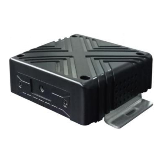
I. Infrared and Card Slot The front panel functions of the device are shown in Figure 1-1. Figure 1-1 Front Panel Interface Diagram The external buttons and interface diagram on the front panel are shown in Figure 1-2. Table 1-1 Front Panel Interface Description Number Denomination Definition... - Page 12 Figure 1-2 Rear Panel Interface The description of each interface on the rear panel of the device is shown in Table 1-2 Table 1-2 Rear Panel Interface Description Number Panel Definition Interface Power Support DC9-36V wide voltage 4G antenna interface GNSS positioning interface AV/IN1-IN2 (720P\1080P)...
-
Page 13: Chapter 3 Installation Instructions
Chapter 3 Installation Instructions 3.1 Installation Considerations Basic Requirements for Installation All electrical work must comply with the latest electrical regulations, fire regulations and related regulations in the place of use. Be sure to turn off the power of all related equipment during installation. Description Cable Requirements It is recommended that the installation cable is in the same direction as the original vehicle cable, and... -
Page 14: Installation Tools
installed in a well-ventilated location to facilitate heat dissipation. Space: Reserve the space needed for air circulation, heat dissipation, flip cover, etc. Placement angle: Place the forensic host horizontally. Any other angle installation method may damage the equipment. Fixing: It is recommended to use the national standard M4 combination screw to fix it. All fixing screws must be tightened in place to avoid loosening after long-term driving and bumping, causing the recorder to fall Description... -
Page 15: Install 4G Card
metal piece facing up. The TF card slot 2 is inserted in the opposite way to the TF card 1. 3.4.2 Install 4G Card Attention Please power off before unplugging and inserting the SIM card If you choose to use the 3G/4G function, please install the 3G/4G card and 3G/4G antenna. The 3G/4G card slot is located on the front panel of the recorder and the antenna interface is located on the rear panel. -
Page 16: Chapter 4 Wiring Instructions
Installed on the lower edge platform of the front windshield of the vehicle and fixed with neutral silica gel. When adjusting the antenna position, ensure that at least 4 satellites have a signal strength of more than 35 dB. Chapter 4 Wiring Instructions 4.1 Power Wiring Attention In order to ensure the correct wiring, please ask the vehicle manufacturer for the connection... -
Page 17: Timer Shutdown
terminal to confirm whether the connection is correct The following figure shows the test wiring and the actual loading power supply wiring: Note: ITH-M525 has no physical switch button, it can be turned on when the power is turned on, and turned off when the power is disconnected 4.1.2 Timer Shutdown For timing shutdown configuration, please refer to "Operation Manual"... -
Page 18: Chapter 5 Active Safety Function Details
Description For IO related function configuration, please refer to "Operation Manual". Chapter 5 Active Safety Function Details 5.1 DMS Driving Analysis System Distracted driving, identifying bad driving behaviors such as watching the driver from left to right. Make phone calls, identify the calling behavior of the driver. ... -
Page 19: Adas Lane Safety Warning
5.3 ADAS Lane Safety Warning FCW (Forward Collision Warning), which judges the potential collision risk by sensing and calculating the distance between the vehicle and the preceding vehicle during driving, and immediately issues a warning. Safe distance warning, the distance of the vehicle ahead is detected by the ADAS algorithm, when ... - Page 20 There are 4 screens by default when starting up. Under the monitoring screen, it is used to switch between four screens, eight screens and single screen; press the 田 key field key to display 8 screens; press the number keys 1, 2, 3, 4, 5, 6, 7, 8 Switch to single screen CH1, CH2, CH3, CH4, CH5, CH6, CH7, CH8 respectively Up, down, left and right arrow keys...
-
Page 21: Chapter 7 System Operation And Settings
Chapter 7 System Operation and Settings 7.1 User Login The set password switch is turned on, press the login button to pop up the login menu, the device number is displayed by default, and the entered password is used to distinguish the user identity, enter the correct password and press the login button to enter the setting interface User identities are distinguished by passwords, which are divided into administrators and ordinary ... -
Page 22: Main Menu
Digital input can be entered directly by pressing the digital key on the remote control or by using a soft keyboard. Alphabetic and non-numeric input must be achieved with a soft keyboard 7.2.1 Main Menu Display all main setting items: general settings, development and application, device management, network management, record and storage, AI and alarm, system and security, system information 7.2.2 General Settings Including sub-menus: Date and Time, terminal management, Server, 4G setting... -
Page 23: Date And Time
7.2.3 Date and Time You can manually set the time, and set different time calibration methods Date format: three formats, namely year/month/day, month/day/year, day/month/year, press [OK] to switch. Date: Displayed in the format of the selected date, manually proofread with the numeric key. ... -
Page 24: Terminal Management
GPS time calibration: On/off, when the GPS signal is valid, the GPS time calibration is changed to when the GPS status is normal, the system will use the UTC time in GPS for time calibration, and time calibration will be performed every 2 minutes Server time calibration: On/off, the server needs to have time calibration server module;... -
Page 25: Server Settings
The installation terminals report to different platforms with different ID Numbers. The terminals report to beidou positioning video platform, and the mobile phone number is the unique ID of the platform when the platform adds vehicles 7.2.5 Server settings Connection Center Server Settings BB proto main: Report the IP address and port of the BB proto main. -
Page 26: Settings
7.2.6 4G Settings Select the module system, and the dial-up parameters default to the Chinese domestic public network dial-up parameters. Access point information can be entered on the private network. 7.3 Development and Application Including submenu: switch machine, cloth standard parameters, national standard parameters, log query, configuration management. -
Page 27: Power On /Off Settings
7.3.1 Power On /Off Settings Mode: Ignition mode/timing mode/standby mode/sleep mode, press [OK] to switch and select. Ignition mode: The car key control device turns on and off, turns on the device starts and turns off the device enters the standby state. Timing mode: The device starts to work normally at the set timing power-on time, and the device stops working and enters the standby state at the timing power-off time. -
Page 28: Bubiao Protocol
7.3.2 Bubiao Protocol Protocol type: Press [OK] to select Beidou and 808. Recorder version: Press [OK] to select 2003 and 2012. Upload the main stream: start/close the stream uploaded to the platform server. Heartbeat interval: upload to the platform to refresh information according to the set time. ... -
Page 29: National Protocol Parameter
7.3.3 National Protocol Parameter Upload Main Stream: turn on/off the stream uploaded to the platform server. Heart Interval: upload to the platform to refresh the information according to the set time Report Interval: Upload to the platform to report the device status according to the set time. ... -
Page 30: Log Search
7.3.4 Log Search Begin and End: Select and search to view the log by entering the time. View the host running log in the time display list. 7.3.5 Parameter Management Export parameter: Export device configuration files to SD card, and import parameter ... -
Page 31: Equipment Management
Import parameter: Import the configuration file from the SD card to the device, which can simplify the manual configuration of parameters for multiple devices that need the same settings. Reset: restore configuration parameters to factory settings. Export log: Export device log to SD card ... -
Page 32: Other Peripherals
232 Serial port: The terminal belongs to the serial port of short-distance transmission channel (generally connected with card reader and printer). 485 serial port: The terminal belongs to the long distance transmission channel serial port (generally connected to the PTZ). Select the peripheral connected in the corresponding serial port, and baud rate and other automatic display as the default parameters. -
Page 33: Network Management
7.5 Network Management Submenu includes central settings, wire management, WIFI management, and 4 G settings 7.5.1 Central Settings See 7.2.5 for details. -
Page 34: Lan Management
7.5.2 Lan Management Network priority setting and local IP setting The M525 series supports access to wired networks. WIRED: Wired network reports server priority settings. WIFI: WIFI reports the priority setting of the server. 4G: 4G signal report server priority setting. ... -
Page 35: Settings
Mode selection: DHCP/hotspot/prohibited/manual, DHCP mode can be connected to WIFI, hotspot mode is used for mobile phone connection for engineering treasure debugging. Authentication mode: select the encryption method corresponding to the wireless router to be connected. SSID: The name of the WIFI. ... -
Page 36: Basic Information
7.6.1 Basic Information Basic recording parameter settings Recording mode: power-on recording, timing recording, alarm recording, the three recording modes are switched by pressing the [OK] key. Start-up recording: The device starts recording automatically when it is turned on. Timed recording: start recording within the set timed recording time period, and no recording at other times. -
Page 37: Main Stream
Alarm recording: when an alarm is generated, the device starts recording, and no alarm is generated without recording. Automatic coverage: turn on/off, press【OK】key to switch optional. ON: When the storage disk is full, it will overwrite the oldest video file and continue to record. OFF: After the storage disk is full, stop recording, and will not overwrite the earliest recording Packing time: Adjust the packing time of terminal equipment recording according to the time you ... -
Page 38: Sub Stream
Enable: Open : Indicates that the channel is turned on. Close: It means that the channel does not record, and no video will be recorded if there is video loss. Resolution: select the local video resolution. Frame rate: Indicates the number of video frames per second, PAL system is 1~25 frames/sec, ... - Page 39 Enable: Open: Indicates that the channel is turned on. Close: It means that the channel does not record, and there is no video loss and no log will be recorded. Resolution: Select the resolution of uploading server video. ...
-
Page 40: Timing Record
7.6.4 Timing record Set timing recording time period You can set up to 4 recording time periods per day. Repeat: Set to select Monday to Sunday, or multiple selections, the time period is valid for 7 days from Monday to Sunday. Time period setting: The start time of the time period cannot be greater than the end time. -
Page 41: Storage Management
7.6.5 Storage Management Video: According to the settings, select the main video/sub stream video. Priority: According to the set level, the video type is stored to the storage device first. The priority is divided into very high, high, medium, low, and very low. 7.6.6 Channel Management OFF: Indicates that the channel does not record, and there is no video loss and no log will be ... -
Page 42: Video Playback
recorded Volume: Set to modify the volume of the channel. Resolution: According to the resolution setting of the camera, they are D1, 720P, 1080P, AUTO. Output format: Switch between PAL and NTSC formats. 7.6.7 Video playback Play back video files stored in this unit Recording type: all recording/normal recording/alarm recording/classified fault recording. -
Page 43: I/O Alarm
7.7.1 I/O Alarm Type: Select the type of access signal. Level: level trigger, low level, 0~4V; high level, 4~25V; set high and low levels according to the connected peripherals, set to low level, the device detects low level input An alarm will be generated;... -
Page 44: Speed
7.7.2 Speed Speed source: GPS speed/pulse speed. To select the pulse speed, you need to connect the speed pulse signal. GPS source: GPS positioning information source selection. Pulse coefficient: pulse speed of vehicle is one kilometer, need to set up speed source for vehicles. ... -
Page 45: Acceleration
7.7.3 Acceleration Separate detection and alarm on the acceleration 3D X, Y, Z axis, when the terminal is installed, you can choose to correct the current position. Enable: whether to detect alarms. Threshold value: alarm will be generated if the threshold value is exceeded. ... -
Page 46: Voltage
7.7.4 Voltage Low voltage alarm: Low voltage alarm will be generated when the detected voltage is lower than the threshold value. High voltage alarm: If the detected voltage is higher than the threshold, a high voltage alarm will be generated. -
Page 47: Apc
Speed threshold: When the vehicle speed exceeds the set threshold, the driving behavior analysis algorithm is activated. Sensitivity: Take smoking as an example. High-sensitivity may have 10 consecutive frames of smoking action images, which is judged as smoking, and low-sensitivity may require 20 consecutive frames of smoking action images to judge smoking. -
Page 48: Systems And Security
Note: This function is mainly used for bus passenger flow statistics up and down the number of guests. 7.8 Systems and Security Submenus include: time Settings, volume Settings, password Settings, about the device, display 7.8.1 Time Setting See 7.2.3 for details... -
Page 49: Volume Setting
7.8.2 Volume Setting Network intercom output: volume setting during video playback Stop announcement output: use the bus version software, the sound setting of the external speaker announces the stop TTS output: TTS voice broadcast volume setting Playback volume: volume setting during video playback ... -
Page 50: Password Setting
7.8.3 Password Setting Enable: turn on/off; choose to turn off, without entering a password, press [LOGIN] key to log in successfully to the setting interface. respectively set the user password and the administrator password, the password for the 6 ... -
Page 51: Display
7.8.5 Display Set boot layout and notification bar display settings Boot layout: You can set the video interface such as four-square grid/ nine-square grid. Icon Disply: Set the items displayed in the notification bar. ... -
Page 52: System Information
7.9.1 System Information The sub-menu includes: location information, storage status, power status, interface status, and network information. 7.9.2 GPS Information You can view the current positioning details, such as whether the positioning status is normal, the current latitude and longitude, speed, and GPS/BD signal reception... -
Page 53: Store Status
7.9.3 Store Status You can see the current state of the existing storage device, used capacity, and available capacity 7.9.4 Power status You can see the current supply temperature, voltage and ACC voltage... -
Page 54: The Interface Status
7.9.5 The Interface Status View the device I/O interface status 7.9.6 Network Information You can view the current 4G connection status, signal strength, whether it is connected to the reporting server, the reported primary and backup server, mobile phone number, and used traffic. -
Page 55: Chapter 8 Dms/Adas Test
Chapter 8 DMS/ADAS Test 8.1 DMS Camera Installation 1. Before calibrating the fatigue detection lens, locate the approximate installation position, that is, the position of the center console to the right in front of the driver. 2. The distance between the fatigue detection lens and the driver’s eyes is between 60-80CM. It is best to use self-tapping screws for the base. -
Page 56: Dms Camera Calibration
8.2 DMS Camera Calibration DMS camera calibration can be calibrated through an external screen or mobile phone engineering treasure APP, as long as the driver's face is in the center of the lens. Confirm that the algorithm is activated before the test, as shown in the figure below, the red box on the screen does not prompt "DMS is not activated".. -
Page 57: Dms Face Recognition
8.3 DMS Face Recognition Connect the external display screen to the terminal, use the remote control /‖ to enter the shortcut control page, press the shortcut key 9 to enter the test page, and perform face recognition and driving behavior analysis tests (driving behavior analysis includes smoking, calling, closing eyes, yawning, look around, put head off). -
Page 58: Adas Lane Test
8.5 ADAS Lane Test 1. Detect the road status through ADAS cameras to realize front vehicle collision warning (FCW), lane departure warning (LCW), (FCW). The driver is reminded, and related events are reported to the platform at the same time, combined with the driver's identity and vehicle location information as evidence.
Need help?
Do you have a question about the ES-M525 Series and is the answer not in the manual?
Questions and answers