Table of Contents
Advertisement
Quick Links
Advertisement
Table of Contents

Summary of Contents for Nietz ESD2
- Page 1 ESD2 VARIABLE SPEED DRIVES USER MANUALS...
-
Page 2: Table Of Contents
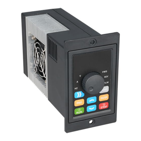
PREFACE CONTENTS First of all, thank you for purchasing series frequency converters of our company! ESD2 Chapter 1 Introduction of Frequency Conversion ............1-2 series frequency converter is a simple and smart frequency converter, which can control AC asynchronous ESD2 motor by V/F, and is suitable for simple places such as assembly line and fan. This manual introducesthe configuration 1.1 Name of each part of frequency converter ..............1... -
Page 3: Chapter 1 Introduction Of Frequency Conversion
K VA :200~240VAC,50/60Hz Single phase power supply 3 . 0 2 . 3 1 . 6 0 . 2 ESD2-0R2G1; 0.2kw 3 . 8 3 . 2 2 . 1 0 . 4 ESD2-0R4G1; 0.4kw 5 . 6 4 . 0 3 . -
Page 4: Chapter 2 Description Of Control Loop
Chapter 2 Description of Control Loop 2. 2 C o n tro l Te rm i n a l s a n d F u n cti on D e s cr i p ti o n Table2-1 -2 Control Loop Terminal Description 2. -
Page 5: Chapter 3 Key Description
Chapter 3 Key Description 3. 3 Ke y F u n ct i o n D e s cr i p ti o n 3.1 Introduction to Operation and Display Interface Table 3-1 Key Function Description N a m e D e s c r i p t i o n Function Settings Enter Key, Exit Key FUNC... -
Page 6: Chapter 4 Function Parameter Table
Factor y Function N a m e C o n t e n t S e t R a n g e Change C h a p t e r 4 F u n c t i o n Pa r a m e t e r Ta b l e Settings Code 2.0~16.0KHz... - Page 7 Factor y Factor y Function Function N a m e C o n t e n t S e t R a n g e Change N a m e C o n t e n t S e t R a n g e Change Settings Settings...
- Page 8 Factor y Factor y Function Function N a m e C o n t e n t S e t R a n g e N a m e C o n t e n t S e t R a n g e Change Change Settings...
- Page 9 Factor y Factor y Function Function N a m e C o n t e n t S e t R a n g e N a m e C o n t e n t S e t R a n g e Change Change Settings...
- Page 10 Monitoring Parameters Factor y Function N a m e S e t R a n g e M i n i m u m u n i t Change Settings Code Factor y Function N a m e S e t R a n g e M i n i m u m u n i t Change Settings...
-
Page 11: Chapter 5 Error Codes
Chapter 6 Communication Protocol C h a p t e r 5 E r r o r C o d e s (the following data are all hexadecimal) 6.1 RTU Mode and Format F a u l t c o d e N a m e When the controller communicates on Modbus bus in RTU mode, every 8-bit byte in the information is divided into 2 4-bit hexadecimal characters. -
Page 12: 03Read Function Mode
function instruction address definition data meaning instruction function instruction address definition data meaning instruction 2106H Output Voltage (1 Decimal) 00: No exception Analog InputAI(two decimal places) 2107H 01: Module Failure 2108H Reser vation 02: over voltage 03: Temperature fault Reser vation 2109H 04: Frequency converter overload Read out trouble... -
Page 13: Write Function Mode
Analysis of this data: Chapter 7 Warranty Agreement 01H is the address of the inverter 03H is read function code 1. This product will be guaranteed for 18 months (except for exported/non-standard machine products) 04H is the product of read entries * 2 1770H is read 2102H (set frequency) data under normal use environment (without moisture and dust) from the date of purchase by the user from the 0000H is reading data of 2103H (output frequency... -
Page 14: Chapter 8 Product Warranty Card
Chapter 8 Product Warranty Card U n i t A d d r e s s : : Company Name: : Contact: : Customer Name Contact number: : Po s t a l C o d e : : P a r t N o . : : Body bar code (pasted here): Product Information...
Need help?
Do you have a question about the ESD2 and is the answer not in the manual?
Questions and answers