Table of Contents
Advertisement
Quick Links
Advertisement
Table of Contents

Related Manuals for Scott TX32


Summary of Contents for Scott TX32
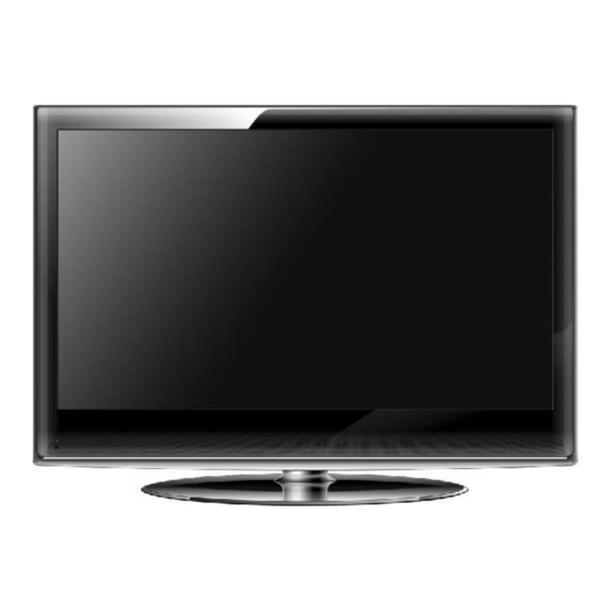
- Page 1 LCD TV TX32...
- Page 2 To our customers LCD (Liquid Crystal Display) screens, like plasma and conventional CRT (Cathode Ray Tube) screens, are also susceptible to ‘screen burn-in’ or ‘image retention’ which can be found on the screen as visible fixed lines and shades and can’t be removed. To avoid such permanent damage to the screen, it is advisable to take the following preventive actions: (1) Avoid displaying still (inactive) images for more than two hours.
-
Page 3: Table Of Contents
Warning-------------------------------------------------------------------------------------------2 Safety Instructions------------------------------------------------------------------------------3-4 Introduction--------------------------------------------------------------------------------------- 5 Connection Operations------------------------------------------------------------------------- 6-10 Remote Control----------------------------------------------------------------------------------- 11-12 Specifications---------------------------------------------------------------------------------------13 Signal Mode---------------------------------------------------------------------------------------- 14 TControl board specification-------------------------------------------------------------------- 15 Function Keys/Receiver PCB------------------------------------------------------------------- 16 Main board SCH------------------------------------------------------------------------------------ 17-25 Main board PCB------------------------------------------------------------------------------------ 26-29 Power Supply board SCH------------------------------------------------------------------------- 30 Power Supply board PCB------------------------------------------------------------------------ 31-36 Power Supply board Specification------------------------------------------------------------- 37-43 Control board Specification---------------------------------------------------------------------- 44-51 Factory menu--------------------------------------------------------------------------------------- 52-53... -
Page 4: Warning
Warning Warning CAUTION RISK OF ELECTRIC SHOCK RISK OF ELECTRIC SHOCK DO NOT OPEN DO NOT OPEN WARNING: TO REDUCE THE RISK OF ELECTRIC SHOCK DO NOT REMOVE COVER(OR BACK). NO USER SERVICEABLE PARTS INSIDE. REFER TO QUALIFIED SERVICE PERSONNEL. The lightning flash with arrowhead symbol, within an equilateral triangle, is intended to alert the user to the presence of uninsulated”dangerous voltage”within the products enclosure that may be of sufficient magnitude to constitute a risk of electric shock to persons. -
Page 5: Safety Instructions
Safety instructions Safety instructions Safety instructions WARNING : WARNING : TO Reduce The Risk Of Fire Or Electric Shock, Do Not Expose This Apparatus To Rain Or Moisture. Apparatus shall not be exposed to dripping or splashing and no objects filled with liquids, such as vases, shall be placed on the apparatus. - Page 6 Safety instructions Safety instructions continued Safety instructions continued 12. Use only cart, stand, tripod, bracket, or table specified 14. Refer all servicing to qualified service personnel. by the manufacturer or sold with the apparatus. Servicing is required when the apparatus has been damaged in any way.
-
Page 7: Introduction
Introduction... -
Page 8: Connection Operations
Introduction Connection Options RF IN SCART1 SCART2 MAIN POWER BUTTON Switch of the power supply AC IN AC input socket HDMI INPUT Connect the HDMI output jack of PC and DVD PC-RGB INPUT Connect the PC-RGB output jack of PC PC AUDIO INPUT Connect the Audio output jack of PC EA PHONE... - Page 9 Introduction External Equipment Connections Power Cord Connection - Connect the power cord correctly as shown. - Press the POWER switch of your LCD TV to switch on the LCD TV. The power indicator on the front panel lights up in Antenna Connection - Antenna or Cable Service without a Cable Box Connections - For optimum picture quality, adjust antenna direction if needed.
- Page 10 Introduction AV/S-VIDEO INPUT Connection NOTE: All cables shown are not included with the TV. - Connect the VIDEO and AUDIO output jack of the DVD or TV Back VCR to the AV IN jacks on the set using the RCA cable. - Match the jacks colors: Video=yellow, Audio left=white, and Audio right=red.
- Page 11 Introduction Y/Pb/Pr INPUT Connection NOTE: All cables shown are not included with the TV. - Connect the VIDEO and AUDIO output jack of the DVD or VCR to the AV IN jacks on the set using the RCA ca- TV Back ble.
- Page 12 Introduction PC Connection - This TV provides Plug and Play capability, meaning that the PC adjusts automatically to the TV’ s setting. The TV sends configuration information (EDID) to the PC using the Video Electronics Standard Association(VESA) Display Data Cha- nnel(DDC) protocol.
-
Page 13: Remote Control
Remote control 1. Power: Toggles the unit between power mode and on. 2. MUTE : Press to eliminate or restore the TV sound. 3. 0,1~9 / : Channel number/teletext mode pages select (When enter the teletext mode only). 4. ATV/DTV:Press to select ATV/DTV. 5. - Page 14 Remote control 15. PMODE: To change the video picture mode.( Standard,Dynamic,Mild,User) 16. CH+/-: lncrease /Decrease TV channel. 17. INPUT Press to display the source menu. 18. MENU: Display Main OSD M enu. 19. NICAM: Change sound mode.According to the input ATV/ signal,automatic.
-
Page 15: Specifications
Product Model TX 32 Screen Size 32" diagonal Aspect Ratio 16:9 Receive Channel 48.25MHz~863.25MHz External Size 795(W)x23 (D)x580(H) mm (with Stand) Net Weight 11.6 kg (with Stand) Display Resolution 1920(H) x 1080(V) pixels Color 16.7 M colors View Angle 178º(H)/178º(V) Brightness (Peak Value) Typical 420 cd/m (Panel Only) -
Page 16: Signal Mode
Signal Mode A. VGA Mode Horizontal Vertical Resolution Frequency Frequency (KHz) (Hz) 31.50 640 x 480 800 x 600 37.90 1024 x 768 48.40 1280 x 768 48.36 1360 x 768 47.70 B. YPbPr Mode Horizontal Vertical Resolution Frequency Frequency (KHz) (Hz) 480i(640x480) -
Page 17: Tcontrol Board Specification
Video System PAL, SECAM Sound system BG,.,DK,I,L/L’ Max. Storage Channel 200 CH VHF (174MHz – 230MHz) Tuner receiving range UHF (474MHz -862MHz) Input impedance 75 Ω Channel bandwidth 7MHz/8MHz DVB-T Modulation COFDM 2K/8K QPSK, 16QAM, 64QAM Video System MPEG-2 MP@ML Sound System MPEG-1 layer 1,2 EPG, Subtitle, Teletext (EURO),... - Page 24 +3.3V HDMI_VCC_3.3-6 HDMI_VCC_3.3-7...
-
Page 33: Power Supply Board Pcb
32" Power supply boards PCB... - Page 34 32" Power supply boards PCB...
- Page 35 32" Power supply boards PCB...
- Page 36 32" Power supply boards PCB...
- Page 37 32" Power supply boards PCB...
- Page 38 32" Power supply boards PCB...
-
Page 39: Power Supply Board Specification
32" power supply specification Electrical Specification History Description REV. Date Drawn Mechanical Electrical Approved SPEC. ISSUE XiongC HuYF ZhouY Tonyhsieh Nov.28.’08 MODEL NO. FSP180-4H02 SHEET 1 OF 6... - Page 40 32" power supply specification Electrical Specification Electrical Requirements 1. Input Characteristics: ITEM CONDITION SPECIFICATION 1.1 Normal Rated Input Voltage 100Vac to 240Vac 1.2 Input Voltage Range 90Vac to 264Vac 1.3 Input Frequency Range 47Hz to 63Hz 1.4 Input Current Harmonic EN61000-3-2 / GB17625.1 D 1.5 Input Current 100Vac / maximum load...
- Page 41 32" power supply specification Electrical Specification 2. Output Characteristics: ITEM CONDITION Output current 2.1 Output Rated :( Standby mode) ON/OFF: Low or open(<0.5V) Output Output Voltage Ripple &noise Min. Max. Peak +5Vsb 4.75V – 5.25V 100mV 0.08A 2.2 Output Rated :(On mode) Output current ON/OFF: High(>2.5V) Output...
- Page 42 32" power supply specification Electrical Specification 3. Protection Characteristics: ITEM CONDITION SPECIFICATION 3.1 Short Circuit Protection (SCP): The PSU will enter into shut down that means no Auto-recovery or latch off output while short circuit happened at output terminal. The PSU will enter into shut down while the No broken, no smoke.
- Page 43 32" power supply specification Electrical Specification 4. Environmental Characteristics: ITEM CONDITION SPECIFICATION 4.1 Electric Fast Transients: Impulse: 1KV applied to AC line , pulse Normal operation shall be Refer to EN61000-4-4 Duration 50nS period 5 min Continued. 4.2 Lightning Surge: 2KV applied between L and FG, N and FG , No smoking and fire.
- Page 44 32" power supply specification Electrical Specification 5.Mechanical Characteristics: ITEM CONDITION SPECIFICATION 5.1 Dimension (Length x Width x Height) 210x110x28.5 mm 5.2 Input AC connector (CN1) A3963WV2-3P-D 2PIN 5.3 Output DC connector CNS1 (A2501WV2-10P or EQU) pin 1: ON/OFF pin 2: pin 3: pin 4: +5.2V...
- Page 45 32" power supply specification...
-
Page 46: Control Board Specification
Control board Specification 1. GENERAL DESCRIPTION 8M06-06B is a multi-purpose LCD/PDP TV control board; it supports LCD panels between 26” -- 56” and PDP panels with single/dual LVDS interface. It supports resolution up to 1920x1080. 8M06-06B supports DVB-T, dual HDMI, dual SCART, CVBS, PC, YPbPr S-Video, Analog TV. It includes an audio amplifier which can support 2X10W (8 ) output. - Page 47 Control board Specification CVBS S-VIDEO L/R RCA input 0.5 Vrms YPbPr/YCbCr Video System PAL/NTSC/SECAM VIDEO OUTPUT CVBS 1.0 Vp-p Video level Frequency 100Hz - 10000Hz @ 3dB (1KHz 0dB reference signal) response Max Output 2x10 W(8 ) THD N<10% AUDIO OUTPUT power CVBS Audio level...
- Page 48 Control board Specification 3. FUNCTION LAYOUT TOP VIEW OF LCD CONTROL BOARD NOTE: The optional connectors and terminals are marked with “*”. HEADP HDMI1 RF Input HDMI2 RGB in Full-SCART audio Half-SCART HONE input INTERFACE FUNCTION DESCRIPTION NOTE: The optional connectors and terminals are marked with “*”. DESCRIPTION DESCRIPTION...
- Page 49 Control board Specification 4. PCB DIMENSION The height of the control board is 27.0 mm.
- Page 50 Control board Specification 5. KEY BOARD AND IR BOARD SCHEMATICS 6. INTERFACE DEFINITION...
- Page 51 Control board Specification...
- Page 52 Control board Specification...
- Page 53 Control board Specification 7. CONFIGURATION & GENERAL PRECAUTIONS Relative humidity: 80%. Storage temperature: -10~+60 °C. Operation temperature: 0~+40 °C. Protect the control board from static; it may cause damage to the IC. Disconnect the TV before the power supply of panel is connected correctly. Do not drop any metal on the control board when it is working.
-
Page 54: Factory Menu
Introduction of Factory Menu... - Page 55 Method of Entering the Factory Menu 1,Power on the LCD TV at normal mode. 2,Press Input Key, and the screen display the main menu, after that press the numeral key 2580 ,the following information will be displayed on the left top corner of the screen.
-
Page 56: Mstar Upgrade And Debugging
MSTAR upgrade and debugging SINHO 1:Preparation for upgrade (1), Mstar hardware upgrades tools and USB cable、VGA cable. (2), Mstar hardware upgrade drive and software upgrades tools. (below) (3), Main board and power supply (MSTAR)Soft Updata driver.rar 2, Hardware upgrade drive install (1), Please connect hardware upgrade board with USB of computer by USB cable, then it will appear “Recognition to the hardware”... - Page 57 (3), Please pay attention. In the installation process, choose the one promoting , Please choose the drive where it is to install.
- Page 60 (4), In the install process, you must do the 3 three times, after that, the installation finishded. Upgrade Process: (1) Choice of hardware board jump apparatus: Choose P.11 and P.4 as picture.shown: P.11 VGA port USB port 4pin neilsbed NOTE upgrade board jump risk should arrcording to previous picture.
- Page 61 The first way 4pin line which connected with AD Board and upgrade board Use one 4PIN line to connect the AD board and upgrade board. For Mstar6M19 4pin neilsbed CN403 ----- 4pin neilsbed ----- ----- CN403...
- Page 62 (2) Open the upgrade window as picture. shown, and choose Config first to click "Use USB"..“Auto release USB”, and pls ensure to choose “Port Type èUSB”,“Speedè(5 we recommend to choose Speed 10 45)”...
- Page 66 At last, please choose “Auto” and select “Blank Read File Program Exit ISP Erase Device All Chip” like the picture below, please pay attention that don't select “Reconnect”.
Need help?
Do you have a question about the TX32 and is the answer not in the manual?
Questions and answers