
Related Manuals for Lauda Versafreeze VF 15040

Summary of Contents for Lauda Versafreeze VF 15040
-
Page 1: Operating Instructions
Operating Instructions Versafreeze Freezer Cabinets VF 15040, VF 60040, VF 70040, VF 15085, VF 60085, VF 70085... - Page 2 2 / 44 Versafreeze Freezer Cabinets 07/2021...
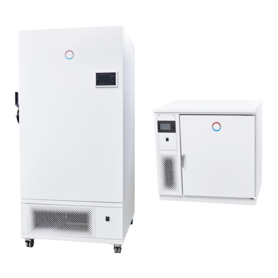
- Page 3 LAUDA-GFL Versafreeze Freezer Cabinets for the long-term storage of organic substances, for example, operate silently and with exceptional reliability. Insulation consisting of vacuum insulation panels and polyurethane foam is the key to its eco- nomical energy consumption. The refrigeration compartment is made entirely of stainless steel.
- Page 4 4 / 44 Versafreeze Freezer Cabinets 07/2021...
-
Page 5: Table Of Contents
Table of contents Operating Instructions ..................................1 Using the freezer cabinets................................ 7 Intended use ..................................7 Improper use ..................................7 Warranty ....................................7 Before starting up ..................................7 Location of the freezer cabinet ............................... 8 Under table installation (only applies for VF 15040 and VF 15085) ..............9 Operating voltage and electrical connection ........................ - Page 6 10 Disposing of old appliances ..............................25 11 Technical data ..................................26 12 Circuit diagram ..................................28 13 Spare parts list ..................................34 Freezer cabinet VF 15040 / VF 15085 ........................34 Freezer cabinet VF 60040, VF 60085 / VF 70040, VF 70085............... 36 Elektrical Switchgear ..............................
-
Page 7: Using The Freezer Cabinets
The freezer cabinet must not be operated in hazardous areas. LAUDA Freezer Cabinets used in laboratories are not classified as medical devices. They are not subject to national or in- ternational medical device law and must be used accordingly. -
Page 8: Location Of The Freezer Cabinet
Disconnect all poles on the appliance from the power supply before commencing maintenance and repair work (pull the mains plug). The warranty does not cover the free repair of malfunctions resulting from improper installation and handling. Only trained and qualified personnel are permitted to perform service and repair work on refrigeration equipment. -
Page 9: Under Table Installation (Only Applies For Vf 15040 And Vf 15085)
Under table installation (only applies for VF 15040 and VF 15085) The cover panel on the deep-freeze appliance must be removed prior to installation under a tabletop. When the appliance door is open, you can reach the screw connection for the cover by inserting a Phillips screwdriver through the opening on the right side of the upper housing frame. -
Page 10: Operating Voltage And Electrical Connection
Freezer cabinets installed under tabletops must be positioned a minimum of 60 mm away from other appliances or walls so that the aspirated cooling air can circulate freely. Once the freezer cabinet has been moved to its place of installation, it must be secured in position with the locking feet. -
Page 11: Commissioning
Commissioning Caution: Due to the low temperatures in the refrigeration compartment, suitable protective gloves must al- ways be worn when storing and retrieving refrigerated goods. Arms must also be covered. Caution: Do not leave the freezer cabinet keys near the appliance or within the reach of children. Do not store acids and alkalies that can erode the materials, hazardous substances that emit harmful va- pors, or highly flammable and/or explosive substances inside the appliance (DGUV Information 213-850). -
Page 12: Operating And Display Elements On The Touch Screen Unit
Operating and display elements on the touch screen unit The three large colored symbols on the left of the display indicate the ACTUAL temperature at the most important points on the appliance: the refrigeration compartment (blue field) and condenser (purple field), while the orange field shows the voltage of the internal battery. - Page 13 Normal refrigeration LED 1 and auxiliary device LED 2 Status LED 1 Description i symbol green active and no fault during normal refrigeration All other cases, including: Connection failure Collective fault Standby Status LED 2 Description Snowflake symbol green active and no fault in the auxiliary device yellow Refrigeration compartment temperature is too high.
-
Page 14: Switching The Appliance On And Off
Switching the appliance on and off The appliance can only be switched on and off from the user profile "User" (see points 6.3 and 6.4 in the operating in- structions). Switch on the appliance by setting the main switch (see point 5 of the operating instructions) to position "I". Approx. -
Page 15: Switching The Appliance On And Off
ADMIN All data and settings that were preset by the manufacturer of the freezer appliance, such as the permitted or possible set point limits for the refrigeration compartment temperature, are stored under the "ADMIN" user profile. The operator cannot modify the settings in this profile. 6.4.1 Switching the appliance on and off Once the user profile has been changed, the display switches to the start screen. -
Page 16: Language Selection
Language selection The only languages currently available are German and English Proceed as follows: Menu Settings Language After selecting the language, press the switch below the additional LED display. Touch VF XXXYY on the display to switch to the controller view. Refrigeration compartment temperature set point Once the refrigeration device has been switched on at the main switch and the touch screen unit (see above), the dis-... -
Page 17: Changing The Password
Changing the password Only the passwords for a specific user profile and all subordinate levels can be changed from the relevant user profile. An Admin1 can change all passwords, a User can only change the passwords for a subordinate Guest. The number of stars in the yellow padlock at the top of the screen indicates which user profile is currently active. -
Page 18: Function Description
Function description LAUDA Versafreeze freezer cabinet models VF 15040, 60040 and 70040 are equipped with a high-performance com- pressor and operate within a variable temperature range of -0 °C to -40 °C. Models VF 15085, 60085, and 70085 are equipped with two high-performance compressors and operate at a temperature range of -50 °C to -85 °C. -
Page 19: Data Transfer Via Usb
Data transfer via USB In order to carry out a data transfer, the Service or Admin1 user profile must be selected. Proceed as follows: Select Menu Select USB Select Export history Insert USB stick. After the USB stick has been recognized, tap the save symbol. After transferring the data, save and remove the USB stick Internet connection The touch control unit can also send alarms by e-mail. -
Page 20: E-Mail Configuration
7.3.2 E-mail configuration Pressing the: Menu E-mail configuration E-mail server buttons opens a window for configuring your e-mail server settings. Save your entries before exiting. 7.3.3 Alarm management Since all alarms indicating a possible fault may impact the proper operation of the appliance, we always recommend select- ing Alarm 1 or Alarm 2 rather than the Warning setting. -
Page 21: Optional Water Cooling
Optional Water cooling Installation of a heat exchanger (water cooling agent) instead of the condenser. The heat exchanger reduces the heat emis- sion of the unit to the ambient considerably and extends the permissible operating temperature range. The regulation is pressure-controlled by the Freezer. -
Page 22: Setting The Cooling Water Volume Regulator
7.4.1 Setting the cooling water volume regulator The setting of the cooling water volume regulator is only necessary if the in-house cooling water is significantly warmer or colder than it was set in test mode. The value of the cooling water volume regulator set in test mode can be found on the label on the cover of the cooling water volume regulator. -
Page 23: Alarm Limit Values
Alarm limit values Setting a limit value for the door alarm delay Tap the Menu symbol on the touch screen unit. In the parameter level, scroll down to the USr user level, tap parameter A6, set the required limit value, and save. A timer starts when the door is opened. If the timer exceeds the preset delay time, the door alarm is triggered. -
Page 24: Alarm And Potential-Free Contact
Alarm and potential-free contact When a malfunction occurs, an alarm is triggered. Each alarm is issued in the form of an acoustic alarm signal and a visual alarm display. All triggered alarms are stored in the controller. When an acoustic alarm signal is issued, the potential-free alarm contact sim- ultaneously connects to the in-house fault monitoring system. -
Page 25: Care And Maintenance
Before sending any appliances, the owner must submit a legally binding decla- ration that the appliance is free of harmful contamination and hazardous substances resulting from its use. LAUDA-GFL laboratory equipment is intended exclusively for commercial use and must not be disposed of via public dis- posal facilities. -
Page 26: Technical Data
Technical data External dimensions (W x D x H in mm) VF 15040 / 85 904 mm x 776 mm x 865 mm VF 60040 / 85 990 mm x 1035 mm x 1965 mm VF 70040 / 85 990 mm x 1185 mm x 1965 mm External dimensions W (W x D x H in mm) VF 15040 / 85 904 mm x 776 mm x 845 mm... - Page 27 Refrigerant quantity, 1st stage Air cooling VF 15040 R1270 - 145 g VF 60040 R1270 - 145 g VF 70040 R1270 - 145 g VF 15085 R290 - 135 g VF 60085 R290 - 145 g VF 70085 R290 - 145 g Water cooling VF 15040 R1270 - 135 g...
-
Page 28: Circuit Diagram
Circuit diagram Single-board cryostat Touch screen unit Over pressure switch, 1st stage Over pressure switch, 2nd stage Microfuse 1.6 A T Microfuse 1.6 A T Mains switch Main contactor Potential-free contact Compressor, 1st stage Compressor, 2nd stage Fan motor, 1,000 rpm or 1,500 rpm Single-board cryostat A1 Temperature probe PT100 for refrigeration compartment Temperature probe PT100 for condenser... - Page 29 VF15040 07/2021 Versafreeze Freezer Cabinets 29 / 44...
- Page 30 VF15085 30 / 44 Versafreeze Freezer Cabinets 07/2021...
- Page 31 VF60040 / VF70040 07/2021 Versafreeze Freezer Cabinets 31 / 44...
- Page 32 VF60085 / VF 70085 32 / 44 Versafreeze Freezer Cabinets 07/2021...
- Page 33 Touch screen unit Single-board cryostat A1 07/2021 Versafreeze Freezer Cabinets 33 / 44...
-
Page 34: Spare Parts List
Spare parts list Freezer cabinet VF 15040 / VF 15085 Item No. Order No. Article 0011204 Dryer, 1st stage 0011162 Compressor, 2nd stage (model VF15085 only) 0011162 Compressor, 1st stage (models VF15040 / VF15085) 0012175 Fan motor 0011459 Safety pressure switch 0014321 Casters 0011415... - Page 35 07/2021 Versafreeze Freezer Cabinets 35 / 44...
-
Page 36: Freezer Cabinet Vf 60040, Vf 60085 / Vf 70040, Vf 70085
Freezer cabinet VF 60040, VF 60085 / VF 70040, VF 70085 Item No. Order No. Article 0013111K Temperature probe PT100 0011204 Dryer 0014327 Caster without locking device 0011415 Manual stop valve 0014326 Caster with locking device 0012191 Fan motor 0011459 Pressure switch 0011204 Dryer... - Page 37 07/2021 Versafreeze Freezer Cabinets 37 / 44...
-
Page 38: Elektrical Switchgear
Electrical Switchgear Order No. Article 0012095 Lead fleece battery 12 V / 12 Ah 0011459 Pressure switch 0012528 Electronic relay (SSR1 / SSR2) 0012520 Contactor 0012435 Protective cap 0012426 Main switch 0012542 Solenoid valve for models VF 60040 and VF 70040 0012096 Adapter M22 RJ45 socket 0012443... -
Page 39: Auxiliary Equipment
Auxiliary equipment Data logger for monitoring and recording refrigeration compartment temperature The data logger for the external monitoring and recording of refrigeration compartment temperatures is fitted with a PT1000 temperature probe with 3 m long PTFE insulated cable that is introduced into the refrigeration compartment via a feed-through integrated in the appliance or preferably a separate feed-through (optional). -
Page 40: Racks With Loading From The Side
14.2.2 Racks with loading from the side Model Contents Number Order No Number of Number of Cabinet Order No Litres of racks for 1 rack boxes/plates boxes/plates for 1 Box per unit per rack per unit VF 15040 129 l VF 15085 not available for VF 150xx VF 60040... -
Page 41: Notes
Notes 07/2021 Versafreeze Freezer Cabinets 41 / 44... - Page 42 EC DECLARATION OF CONFORMITY Hereby we, LAUDA-GFL Gesellschaft für Labortechnik mbH Schulze-Delitzsch-Str. 4+5 30938 Burgwedel Federal Republic of Germany declare that the below stated Versafreeze Deep Freezers models: VF 15040, VF 60040, VF 70040 VF 15085, VF 60085, VF 70085...
- Page 43 07/2021 Versafreeze Freezer Cabinets 43 / 44...
- Page 44 LAUDA-GFL Gesellschaft für Labortechnik mbH Schulze-Delitzsch-Straße 4+5 ◦ 30938 Burgwedel ◦ Germany Phone: +49 (0) 5139 9958-0 ◦ Fax +49 (0) 5139 9958-21 E-Mail: info@lauda-gfl.de ◦ Internet: www.lauda.de/de/lauda-gfl...
Need help?
Do you have a question about the Versafreeze VF 15040 and is the answer not in the manual?
Questions and answers