
Summary of Contents for FIAMA P3S I
- Page 1 P3S_I Position control for Servo unit USER’S MANUAL AND MAINTENANCE POSITION CONTROLLER “P3S_I” FOR DRIVING OF SERVO UNIT “SERVO.M” Data: 13/01/16 Codice: P3S_I Rev 1.0 page 1/14...
-
Page 2: Maintenance
(petrol, diluents, etc.): using these products could affect the proper mechanical functioning of the instrument. Reparations should be done only and exclusively at the FIAMA technical assistance centre. Calibrations and tests It is advisable to calibrate the instrument periodically, once every working year. -
Page 3: Installation
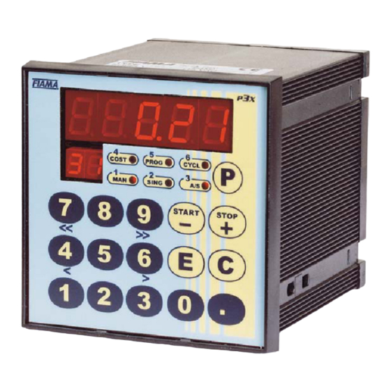
P3S_I Position control for Servo unit Description The controller P3S_I combined to the SERVO_E positioning unit carries out a particular suitable system for the automation of machines that require driving of motorized axes. The inputs of the position controller start, and emergency are opto-insulated. The values are displayed on a high-brightness 5-digit display (range -9999 +99999) while an auxiliary 2-digit display shows the program step during execution or the working constants. - Page 4 P3S_I Position control for Servo unit INPUT DESRIPTIONS The positioning device is controlled by 3 opto-isolated inputs, that are: START it causes the positioning start, active from NA to NC STOP it must be normally closed, if open it blocks or interrupts the positioning RESET the changing over from NA to NC causes the reset or the preset loading according to the zero reset procedure constant.
- Page 5 P3S_I Position control for Servo unit START COMMAND Each time that the positioning device recognize a Start command, starts the selected positioning program. The Start command is as closing the START input in terminal board or to press for a few seconds key START until the axes start to move.
-
Page 6: Working Mode
P3S_I Position control for Servo unit WORKING MODE The P3SI can work in 3 different modes. Automatic mode This mode is that in which the instrument usually is after turning on. If there is only one servomotor on the display appears the current value of axis, while there are more servomotors appear With parameter (see chapter “... -
Page 7: System Register
P3S_I Position control for Servo unit Pressing on key P, if there is only 1 axis, you go out of the writing of programs otherwise you step on the next program and is possible to repeat the proceeding. To esc it is necessary to press key P a second time. Fast access to a program During the choice of a program, instead of increase and decrease the number with + and -, is possible to access directly to any program following this proceeding:... - Page 8 P3S_I Position control for Servo unit : Baud Rate for serial communication with servomotors The programmed value in this constant has to be the same as that set on servomotors (see chapter “Connection scheme of servomotor”). Allowed values: between 1 and 4. 1=2400 2=4800 3=9600...
- Page 9 P3S_I Position control for Servo unit value. To confirm this value press E; otherwise to change it press C to appear a blinking “0”, digit the wished value and confirm with key E. After confirmation or changing of a parameter, step on the next parameter and on the main display appears the name.
- Page 10 P3S_I Position control for Servo unit of proceeding. Suggested Values: <10 . Default values 10 Slope time da 0 a 10 Explanation: is the value that determines the duration of the speed change of the slopes of the system. Suggested Values: 0<Slope time<8. Default values 1.
-
Page 11: Installation Calibration
P3S_I Position control for Servo unit PROCEEDING OF VALUE CALIBRATION The P3SI has an input to carry out the zero-setting of value using the zero index pulse inside of RESET servomotor and an external micro of zero that has to be mounted on the axis at any point inside of available stroke. -
Page 12: Electrical Connection
P3S_I Position control for Servo unit PROCEEDING OF PARAMETERS ADJUSTING OF SERVOMOTOR After the calibration of value following the previous chapter, it is necessary calibrate the parameters of servomotors. Among different configuration parameters, the most has factory values and are suitable for almost all applications;... -
Page 13: Power Supply 24Vdc
P3S_I Position control for Servo unit SERVOMOTOR CONNECTION SCHEME Screw up the 3 screws from the cover. Thread the cable inside its cable gland and carry out the connections as in the following scheme: Power supply 24VDC B1÷B2 = + RS485 serial connection towards P3SI ÷A2 = - RS485... - Page 14 Tel. (+39) 0521.672.341 - Fax. (+39) 0521.672.537 – e-mail: info@fiama.it - www.fiama.it FIAMA srl is not responsible for any damage to persons or things caused by tampering and wrong use and in any case that are not consistent with the features of the instrument.
Need help?
Do you have a question about the P3S I and is the answer not in the manual?
Questions and answers