
Related Manuals for AQUALEAK EMS-01


Summary of Contents for AQUALEAK EMS-01
- Page 1 Read these instructions carefully before using this product. Keep these instructions in a safe place for future reference. EMS-01 Water Leak Detection System Instruction Manual...
- Page 2 Publisher: Aqualeak Ltd. Publication date: 15 February 2021. Version number: 1.1 All possible care has been taken in the preparation of this manual, but Aqualeak, its agents and distributors accept no liability for any inaccuracies that may be found. This manual reflects the state of the product at the publication date below, but further enhancements while in service may mean that the manual does not precisely reflect your system.
-
Page 3: Table Of Contents
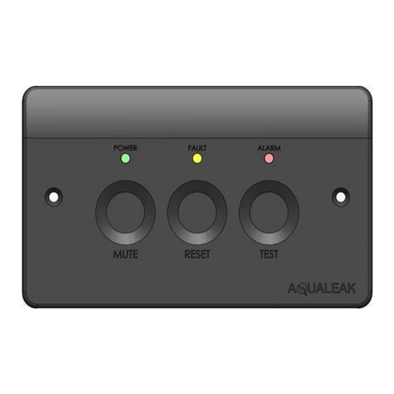
Environmental Monitoring System (EMS-01) Instruction Manual EMS-01 Contents Safety Information ..................... 5 Intended Use ...................... 5 Statutory Obligations..................... 5 Electrical Safety ....................5 Installation Safety ....................6 Post-Installation Safety ..................6 Product Overview ...................... 7 Technical Specifications ..................8 Input-Output Connections ..................9 Single Zone Application Examples ................ - Page 4 Figure 15: Rear of EMS-01 Showing Sensitivity and DIP Switch Settings ........18 Figure 16: DIP Switch Assignments and Default Settings (bottom of unit) ........18 Figure 17: Front Panel of the Aqualeak EMS-01 Water Leak Detection System ....... 20...
-
Page 5: Safety Information
Environmental Monitoring System (EMS-01) Instruction Manual 1 Safety Information For your safety and the safety of others, please ensure that you read the Safety Information below before you install or operate this product. 1.1 Intended Use Only use this product for the intended purpose described in this manual. -
Page 6: Installation Safety
Environmental Monitoring System (EMS-01) Instruction Manual 1.4 Installation Safety RISK OF DAMAGE RISK OF INJURY ✓ ✓ Install the product on a hard, solid, and Be aware of any existing electrical (e.g. level surface. wiring), water (e.g. pipes), or other installations in the vicinity (including within ✓... -
Page 7: Product Overview
Multiple outputs Operation In operation, the EMS-01 continuously monitors the sensing equipment connected to it for both circuit integrity and the presence of water. If a leak is detected, an audible alarm is activated, an LED illuminated, and, if connected, the EMS will report its alarm status to any connected device (BMS/SMS/beacon, valve) via its volt free contacts. -
Page 8: Technical Specifications
Environmental Monitoring System (EMS-01) Instruction Manual 2.1 Technical Specifications EMS-01 Specification Notes Dimensions 146 x 86 x 69 mm Millimetres. Width x Height x Depth Weight 300 g Grams (0.3 Kilograms) Supply Voltage 100-240 VAC Volts / Alternating Current 50-60 Hertz... -
Page 9: Input-Output Connections
Environmental Monitoring System (EMS-01) Instruction Manual 2.2 Input-Output Connections Figure 2: EMS-01 Input-Output Connections Item Name Notes Relay Abbreviations Power Fault Relay NC | NO | COM NO = Normally Open NC = Normally Closed Sensitivity Measure Used with Sensitivity Adjustment... -
Page 10: Single Zone Application Examples
Environmental Monitoring System (EMS-01) Instruction Manual 2.3 Single Zone Application Examples Aqualeak water leak detection and prevention systems are based on a modular design. Parts supplied depend upon intended application and particular requirements. Once the individual components have been selected, the system can be built and installed. -
Page 11: Installation
3.1.2 Power Connections A competent person must power the EMS-01 via an appropriate mains supply at a nominal 230V 50-60Hz, from a spur with a minimum capacity of 8 Amps. This supports switching power to external loads through the 8 Amp Double Pole Double Throw (DPDT) relay. -
Page 12: Sensors And Relays
POWER FAULT RELAY SENSOR INPUT NC|NO|COM Red Core: Left Black Core: Right Figure 6: EMS-01 Rear Panel Showing Sensor / Relay Connections Connect Sensor Cable (SCY) using LC10C and End of Line Sensor Cable EOL Terminator Leader Cable Cable Connection... - Page 13 Environmental Monitoring System (EMS-01) Instruction Manual Connect Sensor Cable (SCY) using LC10/LCB100 and Start of Line Green and white cores not used SENSE TERMINAL LOOP TERMINAL Red Core: +/1 block not used Black Core: -/2 Belden 9534 Cable to Secure cable under clamp...
- Page 14 Environmental Monitoring System (EMS-01) Instruction Manual Connect a Single Environmental Sensing Device Sensor Probe RED EOL SWITCH ‘IN’ position Green and white cores not used LOOP TERMINAL SENSE TERMINAL block not used Red Core: +/1 Black Core: -/2 Secure cable under clamp...
- Page 15 Environmental Monitoring System (EMS-01) Instruction Manual Connect Multiple Environmental Sensing Device Sensor Probes as a Single Zone ESD #3: RED EOL SWITCH ESD #2: RED EOL SWITCH ESD #1: RED EOL SWITCH ‘IN’ position ‘OUT’ position ‘OUT’ position Figure 10: Connecting Multiple ESD Sensor Probes as a Single Zone Connect multiple ESD sensor probes to a single zone as follows: Ensure that the unit is powered OFF.
-
Page 16: Ancillary Devices
3.3 Ancillary Devices 3.3.1 Signalling to an Ancillary Device The EMS-01 can be connected to provide a signal to a range of ancillary devices such as a Building Management System (BMS) or Short Message Service (SMS) alarm unit. ALARM RELAY 1... -
Page 17: 230V Output To An Ancillary Device
Environmental Monitoring System (EMS-01) Instruction Manual 3.3.3 230V Output to an Ancillary Device The EMS can be used to control powered ancillary devices such as a beacon or solenoid valve. Figure 13: Using the EMS to Power a 230V Ancillary Device (Alarm Relay 1: Normally Open) -
Page 18: Configuration
Trimmer Sensitivity Measure Figure 15: Rear of EMS-01 Showing Sensitivity and DIP Switch Settings 4.1 DIP Switch Settings DIP Switch setting changes take effect immediately unless the system is in a state of reporting a fault or leak (i.e. Cable Fault or Leak Mode), or is in Test or Engineering Mode (see Section 5). -
Page 19: Sensitivity Adjustment
Environmental Monitoring System (EMS-01) Instruction Manual 4.2 Sensitivity Adjustment A small flat-head screwdriver should be used to set potentiometer sensitivity. A digital multi- meter (DMM) is also required to measure sensitivity settings during adjustment. The unit sensitivity trimmer provides a means to control the set point at which alarms occur. This can be adjusted to prevent false triggering and manage temporary rises in humidity. -
Page 20: Operation
Configuration of DIP Switch settings will determine sounder, alarm delay, and relay latch activation during operating modes (see section 4.1). Once powered on, the EMS-01 Leak Detector maintains a background timing scheme while continuously monitoring sensor and sensitivity levels. The unit continuously monitors connected Aqualeak sensors to gather batches of data samples which are averaged over time to determine if a cable fault or leak has occurred. -
Page 21: Monitor Mode
Environmental Monitoring System (EMS-01) Instruction Manual 5.1 Monitor Mode Standard mode of operation. Fault and Alarm indicators OFF Touch Button(s) Hold Time Effect Mute Disabled. No effect. Reset Test 3 seconds. Enter Test mode (section 5.5). Table 6: Monitor Mode Touch Button Inputs and Effects 5.2 Fault Mode... -
Page 22: Engineering Override Mode
Environmental Monitoring System (EMS-01) Instruction Manual 5.4 Engineering Override Mode This mode is accessed in Fault or Alarm mode to override the system for a period of 24 hours. This is to allow water to dry out and to unlatch any latched relays (e.g. which may be holding off water via a solenoid valve). -
Page 23: System Testing
Environmental Monitoring System (EMS-01) Instruction Manual 5.6 System Testing For general testing, DIP switches 3 and 4 (Alarm delays) should be disabled. This is to prevent a 1 to 5-minute delay before alarms are raised (see section 4.1). Connect a dry sensor to the unit to prevent inadvertently triggering the alarm. For each of the four tests listed below it is assumed that the unit is powered on and in Monitor Mode (i.e. -
Page 24: Test A Cable Fault (Leader And Sensor Cables)
Environmental Monitoring System (EMS-01) Instruction Manual Test 4 (Engineering Mode) is performed as follows: Trigger Cable Fault Mode (Test 2) or Alarm Confirm all output relays have latched Mode (Test 3). correctly with use of a digital multi-meter. Hold the Mute and Reset buttons together... -
Page 25: Maintenance
6.2 Troubleshooting The table below lists the most common problems and their solutions. If a problem cannot be solved then please call support on +44 (0)1249 715698 or visit our website at www.aqualeak.com. Problem Possible Cause Possible Solution System does not power on. -
Page 26: Warranty
Environmental Monitoring System (EMS-01) Instruction Manual 7 Warranty The Aqualeak Environmental Monitoring System (EMS-01) Water Leak Detector has a 1-year back-to-base warranty as standard, and a 5-year warranty where installed and annually maintained by Aqualeak. The warranty is applicable from the original purchase date and includes repair or replacement if the product is defective. - Page 27 Only for EC countries: Do not dispose of Master Unit and Outstations into household waste! According the European Guideline 2002/96/EC for Waste Electrical and Electronic Equipment and its implementation into national right, measuring tools that are no longer usable must be collected separately and disposed of in an environmentally correct manner.
Need help?
Do you have a question about the EMS-01 and is the answer not in the manual?
Questions and answers