Advertisement
Quick Links
Note to Installer:
Note to Customer:
Skill level:
Product failure due to improper installation is not covered under warranty.
MODELS:
3103XX
8-foot ceiling
3104XX
9-foot ceiling
INSTALLATION REQUIREMENTS
Verify planned equipment location is
Height clearance
Footprint (DxW)
Insert Platform
configuration (DxW)
Olympic Lifting
Insert Platform
configuration (DxW)
Free Space
around Equipment
(recommended)
CUSTOMER SUPPORT
If you have any questions regarding the
after reading this guide, contact Keiser Customer Support:
1 559 256 8000
service@keiser.com
keiser.com/support
315503_A
ASSEMBLY INSTRUCTIONS
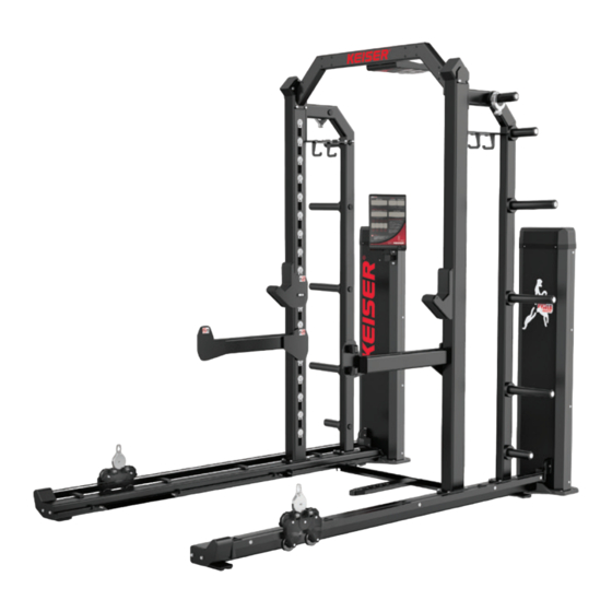
KEISER STRENGTH
HALF RACK
READ CAREFULLY. KEEP THESE INSTRUCTIONS.
Be sure to leave Assembly Instructions with the customer.
Keep Assembly Instructions for future reference.
Professional installation is required by qualified personnel.
3103XX model
a solid, level, and structurally sound surface and
3103XX
8-foot ceiling
9-foot ceiling
96 in (2,439 mm)
108 in (2,743 mm)
61 in x 71 in (1,550 mm x 1,804 mm)
- not applicable -
138 in x 100 in (3,505 mm x 2,540 mm)
Sides*
72 inches
(1,829 mm)
*Multiple Racks may share side Free Space.
Assembly Instructions
3105XX Long Base
8-foot ceiling
3106XX Long Base
9-foot ceiling
meets the following dimensions criteria:
3104XX
3105XX
8-foot ceiling
96 in (2,439 mm)
93 in x 71 in (2,362 mm x 1,804 mm)
98 in x 71 in (2,489 mm x 1,804 mm)
172 in x 100 in (4,369 mm x 2,540 mm)
Front
48 inches
(1,219 mm)
3105XX model
3106XX
9-foot ceiling
108 in (2,743 mm)
Rear
12 inches
(305 mm)
KEISER CORPORATION
2470 S. Cherry Ave.
Fresno, CA 93706
Advertisement

Related Manuals for Keiser 3103XX

Summary of Contents for Keiser 3103XX
- Page 1 (recommended) *Multiple Racks may share side Free Space. CUSTOMER SUPPORT If you have any questions regarding the Assembly Instructions after reading this guide, contact Keiser Customer Support: KEISER CORPORATION 1 559 256 8000 2470 S. Cherry Ave. service@keiser.com Fresno, CA 93706 keiser.com/support...
- Page 2 INTRODUCTION warranty registration. Congratulations on the purchase of your Keiser Half Rack and welcome to the Keiser family. For your safety, and to ensure optimal equipment performance, please read and understand this manual before assembly. If you have any questions regarding assembly after reading this manual, our Keiser Customer Support team will be happy to assist by telephone at 1 559 256 8000, online 24/7 at keiser.
- Page 3 They contain important information. 12. Keiser Corporation is not responsible for damage or serious If unreadable or missing, contact Keiser Corporation for a injury caused by incorrect installation, assembly, or use.
- Page 4 HALF RACK, HALF RACK LONG BASE ASSEMBLY INSTRUCTIONS EQUIPMENT SPECIFICATIONS Size and weight specifications: 3103 HALF RACK 3104 HALF RACK 8-foot ceiling 9-foot ceiling 104 in (2,642 mm) 92 in (2,337 mm) 655 lbs 666 lbs (297 kg) (302 kg) 61 in 61 in 71 in...
- Page 5 HALF RACK, HALF RACK LONG BASE ASSEMBLY INSTRUCTIONS TRAINING SPACE The minimum recommended amount of Free Space around the equipment is 72 inches (1,829 mm) for the sides, 48 inches (1,219 mm) for the front, and 12 inches (305 mm) for the rear (see Figure 2). Half Racks arranged side by side may share the Free Space.
- Page 6 The standard Half Rack assembly configuration may be anchored directly onto concrete flooring at the four anchor points (see Figure 3; anchor bolts not supplied). All other assembly configurations (Insert Platform and Olympic Lifting Insert Platform) requires the Half Rack to be bolted onto the platform (hardware supplied by Keiser Corp.). All Anchors Fasteners: •...
- Page 7 NOTE: Optional Olympic Lifting Insert and Insert Platforms (including optional accessories) not shown. Check for any damage or missing parts. If parts are damaged or missing, contact your local dealer, distributor, or Keiser Customer Support by telephone at 1 559 256 8000.
- Page 8 *Required for closed crate only Unbolt Weight Stacks from Posts Keep bolts/washers for assembly Figure 5. How to Unpack the Half Rack Model 3106XX 9' Half Rack Long Base shown. Bottom Frames and Posts for models 3103XX, 3104XX, and 3105XX have similar appearance.
- Page 9 HALF RACK, HALF RACK LONG BASE ASSEMBLY INSTRUCTIONS ASSEMBLY PROCEDURE TWO-PERSON PROCEDURE: Due to the size of the equipment parts, help is required to safely and successfully complete the assembly procedure. HEAVY OBJECT: Help is required during lifting to avoid muscle strain or back injury. ASSEMBLE YOUR INSERT PLATFORM OR OLYMPIC LIFTING INSERT PLATFORM FIRST See platform assembly diagram included with the platform.
- Page 10 HALF RACK, HALF RACK LONG BASE ASSEMBLY INSTRUCTIONS INSTALL POWER MODULES AND DISPLAY Have your helper raise the Actuator Tab (press Foot Pedal) as you begin to position the Power Module on the Base Plate. Release the Foot Pedal before the Actuator Tab enters the Power Module; pull the wire and air lines through the Bottom Frame.
- Page 11 HALF RACK, HALF RACK LONG BASE ASSEMBLY INSTRUCTIONS CONNECT AIR LINES AND COMMUNICATION WIRE Remove the Bolts and Washers at Bottom Frame. Tilt a Power Module with Bottom Frame to position the Cable Tray. Then, route the Air Lines / Communication Wires and install the Cable Tray. Power Module Bottom Frame Cable Tray...
- Page 12 HALF RACK, HALF RACK LONG BASE ASSEMBLY INSTRUCTIONS POWER DISPLAY CONNECTION CHECK AND BENCH POSITIONER INSTALLATION NOTE: Air Compressor not required to turn on the Power Display. Turn on the Power Display by momentarily pressing both + and – Foot Pedals. RESISTANCE window change from OFF to CLEr >...
- Page 13 HALF RACK, HALF RACK LONG BASE ASSEMBLY INSTRUCTIONS SET POSTS IMPORTANT: DO NOT TIGHTEN BOLTS UNTIL FINAL INSTALLATION. PARTS MUST BE ABLE TO ADJUST FOR EASY BOLT HOLE ALIGNMENT. RIGHT POST (with COMMUNICATION WIRE) Communication Port and Decals face inward LEFT POST RIGHT POWER MODULE...
- Page 14 HALF RACK, HALF RACK LONG BASE ASSEMBLY INSTRUCTIONS INSTALL CROSS BRACE AND TOP POWER DISPLAY IMPORTANT: BEFORE INSTALLATION, CHECK BOLTS AT THE BASE OF THE POSTS ARE NOT FULLY TIGHTENED TO ALLOW FOR EASY BOLT HOLE ALIGNMENT. Route Communication Wire with Coupler through Display Port and install the Cross Brace. Cross Frame Display Port (rear view)
- Page 15 HALF RACK, HALF RACK LONG BASE ASSEMBLY INSTRUCTIONS INSTALL WEIGHT STACK IMPORTANT: BEFORE INSTALLATION, CHECK BOLTS AT ALL POST CONNECTION POINTS ARE NOT FULLY TIGHTENED TO ALLOW FOR EASY BOLT HOLE ALIGNMENT.
- Page 16 HALF RACK, HALF RACK LONG BASE ASSEMBLY INSTRUCTIONS FINAL ASSEMBLY IMPORTANT: PROPERLY TIGHTENED ALL BOLTS. TORQUE SPECIFICATION 3/8-16 IN. (FRAME BOLTS): 25 ft-lbs (34 Nm) Reference Step 5 through Step 7 for all frame bolt locations. 3106XX Half Rack (all other Half Rack models similar) Set Bar Catches, Cantilever Spotting Bars, and Barbell Attachments.
- Page 17 Figure 6. Air System Setup Reference WARNING: Never connect Keiser pneumatic equipment to an air source that is capable of exceeding 120 psi / 8.27 bar. Over pressurizing Keiser pneumatic equipment may cause tubing to burst, breakage of equipment, abnormal operation, or serious injury.
- Page 18 HALF RACK, HALF RACK LONG BASE ASSEMBLY INSTRUCTIONS This page intentionally left blank.
- Page 19 HALF RACK, HALF RACK LONG BASE ASSEMBLY INSTRUCTIONS This page intentionally left blank.
- Page 20 Distribution and copying of this document, use and communication of its contents is not permitted without written authorization from Keiser Corporation. The content of this document is furnished for informational use only, may be subject to change without notice, and should not be construed as a commitment by Keiser Corporation.
Need help?
Do you have a question about the 3103XX and is the answer not in the manual?
Questions and answers