Advertisement
Quick Links
INSTALLATION INSTRUCTION SHEET
MPG-1 Metering Pulse Generator
Y
Output
Status LEDs
Z
S1
Dip Switch
Communication
Status LEDs
MOUNTING POSITION - The MPG-1 can be mounted in any position. Two mounting holes are provided. The
MPG-1 must be mounted in a non-metalic enclosure or somewhere where it can receive the streaming wireless
information from the meter without interference. The MPG-1 must be mounted within about 75 feet from your meter.
Distances vary with building construction and proximity to the meter. For best results, mount as close to the meter
as possible. The pulse output lines from the MPG-1 may be run longer distances, but the MPG-1 should have
uninterrupted access for best results. Choose a mounting location that will not have any metalic parts -- moving or
stationary -- that can affect the RF field.
POWER INPUT - The MPG-1 is powered by an AC voltage of between 90 and 300 volts. For 120VAC, connect the
AC supply's "hot" wire to the L1 terminal. For 208 to 277VAC, connect the AC supply's "hot" wire to the L2 terminal.
Connect the NEU terminal to the AC supply's "neutral" wire. Connect GND to electrical system Ground.
METER INPUT - The MPG-1 receives data from a Zigbee-equipped AMI electric meter that has been paired with a
RAVEn Zigbee USB receiver. The RAVEn USB receiver must be paired with the meter before it can be used. Once
paired & inserted into the USB port, the MPG-1 starts receiving demand information from the meter. (See Page 3.)
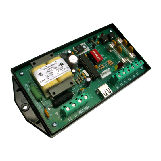
OUTPUTS - Two 3-wire isolated outputs are provided on the MPG-1, with output terminals K1, Y1 & Z1 and K2, Y2,
& Z2. Transient suppression for the contacts of the solid-state relays is provided internally. The output loads should
be limited to 100 mA at 120 VAC/VDC. Maximum power dissipation of each output is 800mW. The outputs are
protected by fuses F1& F2. One-tenth (1/10) Amp fuses (the maximum size) are supplied standard.
OPERATION - See the following pages for a full explanation of the operation of the MPG-1.
SOLID STATE INSTRUMENTS
Revision: 4/21/2018
1
2
3
4
5 6
Serial
Port
USB
Port
a division of Brayden Automation Corp.
6230 Aviation Circle, Loveland, Colorado 80538
Phone: (970)461-9600 Fax: (970)461-9605
E-mail: support@solidstateinstruments.com
V2.12 Firmware
Z2
OUTPUT #2
Y2
K2
Z1
OUTPUT #1
Y1
K1
RS-232 INTERFACE
to programming computer
USB HOST
PORT
GND
POWER SUPPLY
NEU
INPUT
120V
Use one power input ONLY plus Neutral
277V
Zigbee USB
Dongle
P/N: 05908-96007H
Advertisement

Summary of Contents for SSI MPG-1
- Page 1 -- that can affect the RF field. POWER INPUT - The MPG-1 is powered by an AC voltage of between 90 and 300 volts. For 120VAC, connect the AC supply's "hot" wire to the L1 terminal. For 208 to 277VAC, connect the AC supply's "hot" wire to the L2 terminal.
- Page 2 MPG-1 Wiring Diagram To Line Service Entrance MPG-1 Wireless Pulse Generator Electric Wireless Meter Data - 75' max w/Zigbee Radio Out 1 To EMS RAVEn dongle Host Port Out 2 To SCADA To Loads 120-277VAC Power Supply Connections MPG-1W iringDiagram.vsd REVISIONS Brayden Automation Corp./...
- Page 3 Once the settings have been made on the DIP switch and the RAVEn has been inserted into the USB host port, power up the MPG-1 board. The RED LED on the RAVEn dongle will flash for up to 60 seconds while it is establishing communications with the meter.
- Page 4 RAVEn's ability to receive data reliably from the meter. To correct this, change the proximity of the MPG-1 to the meter, move it closer to the meter if possible and eliminate any metalic obstructions between the meter and the MPG-1.
- Page 5 WORKING WITH THE MPG-1 RELAY OPERATING MODES: The MPG-1 Meter Pulse Generator allows the outputs to be configured in either the "Toggle" or "Fixed" pulse output mode. In the Toggle mode, the outputs alternate or toggle back and forth each time a pulse is generated. This is synonomous with the classic 3-Wire Pulse metering and emulates the SPDT switch model.
- Page 6 You will not see the "M160" that you typed in on the screen unless the local echo is enabled on your terminal software. To read back what the value of the multiplier currently in the MPG-1 is, press R and <Enter>. The serial link will return the current multiplier stored in the MPG-1, along with all other system settings.
- Page 7 Programmable Output Pulse Value One of the newest features of the MPG-1 is the capability to set the Output Pulse Value to a value other than those available on the Dip Switch settings. The Programmable Output Pulse value may be programmed from 1 to 99999. The default value of this register is zero (0) which enables the Dip Switches.
- Page 8 To enter the functional or operational mode into the MPG-1, use the S and N commands. Press N <Enter> to set the MPG-1 in the Normal mode. Press S <Enter> to set the MPG-1 in the Signed mode. The serial link to the MPG-1 will return "Output Mode: Signed".
- Page 9 X0<CR> command will disable the reset feature. The default number of time delay violations is 2. List of MPG-1 Commands (?) For help in selecting or using the serial commands with the MPG-1, simply press the ? key. The serial link on the MPG-1 will return a full list of the commands.
Need help?
Do you have a question about the MPG-1 and is the answer not in the manual?
Questions and answers