
Related Manuals for VWR VisiCamB5

Summary of Contents for VWR VisiCamB5
- Page 1 USB cameras INSTRUCTION MANUAL Model European Catalogue Number VisiCamB5 630-2957 VisiCamP6 630-2958 OPTKC-P20CC 630-2959 OPTKC-PF 630-2960 Version: Issued: 07, 02, 2020...
-
Page 2: Table Of Contents
Legal Address of Manufacturer Europe VWR International bvba Researchpark Haasrode 2020 Geldenaaksebaan 464 B-3001 Leuven + 32 16 385011 http://be.vwr.com Country of origin: ITALY Table of Contents Warning Safety Information Package Contents Unpacking Intended use Symbols and conventions Overview VisiCamB5... -
Page 3: Warning
Users should observe all safety regulations of the region. The equipment has acquired the CE safety label. How- ever, users do have full responsibility to use this equipment safely. Please follow the guidelines below, and read this manual in its entirety to ensure safe operation of the unit. Package Contents VisiCamB5 DESCRIPTION QUANTITY Camera USB2.0 cable... -
Page 4: Overview
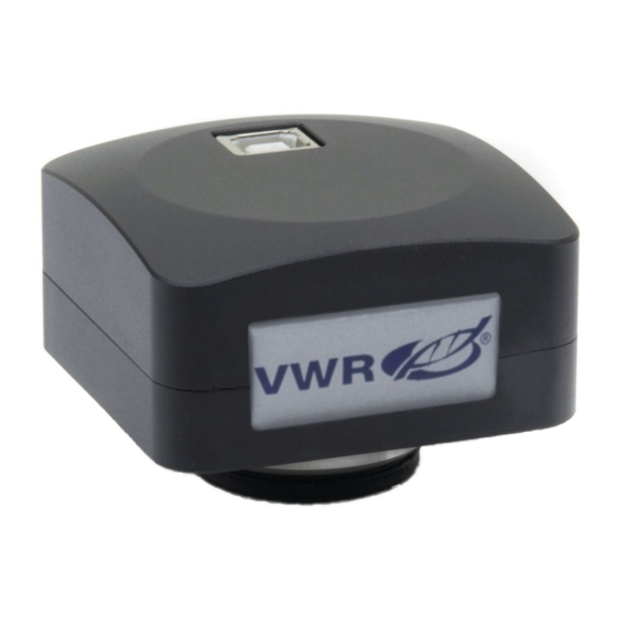
Symbols and conventions The following chart is an illustrated glossary of the symbols that are used in this manual. CAUTION This symbol Indicates a potential risk and alerts you to proceed with caution Overview VisiCamB5 USB 2.0 CABLE SOCKET “C” MOUNT... -
Page 5: Visicamp6 / Optkc-Pf
VisiCamP6 / OPTKC-PF USB 3.0 CABLE SOCKET (BACK OF THE CAMERA) “C” MOUNT OPTKC-P20CC USB3.0 CABLE SOCKET USB2.0 CABLE SOCKET OPERATION LED EXTERNAL POWER SUPPLY SOCKET... -
Page 6: Camera Installation And Settings
Camera Installation and Settings Assembling on microscope 8.1.1 Connection to trinocular port using focusable “C” mount adapter 1. Remove the dust cover from camera and from “C” mount adapter. 2. Screw the “C” mount adapter to the camera’s thread. (Fig. 1) F ig. -
Page 7: Connection To Binocular Or Monocular Head
• Installing on biological microscopes 3. Insert the final part of the projection lens into the empty hole of the photo tube. (Fig. 5) F ig. 5 ig. 5 • Installing on stereomicroscopes 4. Insert the final part of the projection lens into the empty hole of the photo tube. -
Page 8: Using A Biological Microscope
4. Insert the final part of the projection lens into the empty eyepiece sleeve. (Fig. 9) F ig. 9 ig. 9 5. In case of eyepiece sleeve with diameter 30 or 30.5 mm use the adapter rings. (Fig. 10) F ig. 10 ig. -
Page 9: Using A Stereomicroscope With Projection Lens
8.2.3 Using a stereomicroscope with projection lens 1. Use a low power magnification and focus the ① specimen. 2. Reach the highest magnification available us- ing the zoom knob and then focus the specimen again. 3. Turn on the live-view on the camera, without changing the focus on the microscope. -
Page 10: Use Of Drainage Tube (Cooled Versions)
Use of drainage tube (cooled versions) • NOTE: Use the drainage tube only when strict- ly necessary. Cooled cameras sometimes create condensation in- side the camera body during normal use. This condensation may interfere with the correct cre- ation of the image on the sensor. To remove any condensation, act as follows. -
Page 11: Micrometric Slide Vwr005
10. Micrometric Slide VWR005 Micrometric slide, 26x76mm, with 2 scales (1mm/100div. for biological microscopes / 10mm/100div. for stereomicroscopes) 0 1 2 3 4 5 6 7 8 9 10 1 DIV=0.01mm 1 DIV=0.1mm For biological microscopes calibration For stereo microscopes calibration... -
Page 12: Repair And Maintenance
VWR International warrants that this product will be free from defects in material and workmanship for a period of five (5) years from date of delivery. If a defect is present, VWR will, at its option and cost, repair, replace, or refund the purchase price of this product to the customer, provided it is returned during the warranty period. -
Page 13: Disposal
Disposal This equipment is marked with the crossed out wheeled bin symbol to indicate that this equipment must not be disposed of with unsorted waste. Instead it is your responsibility to correctly dispose of your equipment the end of its life cycle by handling it over to an authorized facility for separate collection and recycling. - Page 16 E-mail: info@nl.vwr.com Email: info@pro-lab.com.tr Transformervej 8 New Zealand 2730 Herlev Tel.: 43 86 87 88 Global Science - A VWR Company VWR International Ltd Fax: 43 86 87 90 241 Bush Road Customer Service Centre E-mail: info@dk.vwr.com Albany 0632, Auckland Hunter Boulevard - Magna Park Tel.: 0800 734 100...
Need help?
Do you have a question about the VisiCamB5 and is the answer not in the manual?
Questions and answers