
Subscribe to Our Youtube Channel
Related Manuals for GEA Lagoon Agitator

Summary of Contents for GEA Lagoon Agitator
- Page 1 Lagoon Agitator PTO Agitator Instruction Manual / Installation Instructions (Original instructions) 2010-9015-017 04-2015 engineering for a better world GEA Farm Technologies...
-
Page 2: Table Of Contents
................GEA Farm Technologies Canada Inc. / Division GEA Houle - general equipment warranty . - Page 3 Troubleshooting ............. . . Special personnel qualification required for troubleshooting .
-
Page 4: Preface
Preface About this manual Preface This is a GEA product. GEA is the manufacturer of the Houle product line. This product was formerly known under HOULE trademark. About this manual The manufacturer reserves the right to make changes due to technical developments in the data and images given in this manual. -
Page 5: Manufacturer's Address
Preface Customer service Manufacturer's address GEA Farm Technologies Canada Inc. / Division GEA Houle 4591 boul. St-Joseph Drummondville, Qc, J2A 0C6 +1 819 477 - 7444 +1 819 477 - 5565 geahoule@gea.com www.gea-farmtechnologies.com Customer service Dealer If necessary, please contact your nearest dealer. -
Page 6: Declaration Of Conformity
The undersigned is acting by virtue of power of attorney from the management of: GEA Farm Technologies Canada Inc. / Division GEA Houle, 4591 boul. St-Joseph, Drummondville, Qc, J2A 0C6 This declaration certifies compliance with the guidelines indicated, but does not establish any guarantee in the sense of paragraphs 443, 444 BGB. -
Page 7: Gea Farm Technologies Canada Inc. / Division Gea Houle - General Equipment Warranty
Preface GEA Farm Technologies Canada Inc. / Division GEA Houle - general equipment warranty GEA Farm Technologies Canada Inc. / Division GEA Houle - general equipment warranty Important notice! THIS GENERAL WARRANTY APPLIES TO ALL EQUIPMENT SOLD UNDER THE GEA HOULE TRADEMARK. - Page 8 Preface GEA Farm Technologies Canada Inc. / Division GEA Houle - general equipment warranty 1.5.2 Condition of the limited warranty The Company, through its GEA authorized dealers only (hereinafter referred to as ”Dealer”, reserves the right to either repair or replace all parts deemed defective under the following conditions: 1.
- Page 9 Preface GEA Farm Technologies Canada Inc. / Division GEA Houle - general equipment warranty ● Freight and shipping associated with repair or replacement of equipment under this limited warranty, as well as all costs relating to removal or replacement of any equipment that is welded or affixed permanently to the ground or a building (including, without limitation, labor costs, and costs related to concrete or excavation);...
- Page 10 Preface GEA Farm Technologies Canada Inc. / Division GEA Houle - general equipment warranty 1.5.4 Warranty limitations and exclusion NO WARRANTY, ORAL OR WRITTEN, EXPRESS OR IMPLIED, OTHER THAN THE ABOVE WARRANTY IS PROVIDED IN RESPECT OF THE EQUIPMENT SOLD.
-
Page 11: Safety
Safety Owner's obligation of care Safety Owner's obligation of care This product is designed and constructed while taking into account a potential risk analysis, a selection of harmonized standards and other technical specifications to be complied with in order to guarantee a maximum level of safety. -
Page 12: Explanation Of Safety Symbols
Safety Explanation of safety symbols Explanation of safety symbols Safety symbols draw attention to the importance of the adjacent text. The design of the warnings is based on ISO 3864-2 and ANSI535.6. Safety symbols and key words Danger! The indication ”Danger” signals immediate danger to life or health of personnel. -
Page 13: Basic Safety Instructions
Safety Basic safety instructions Basic safety instructions ● Read and follow the instructions of this instruction manual before performing activities in connection with this product. Keep the instruction manual with this product allowing anyone to refer to it at any time. ●... -
Page 14: Personnel Qualifications
Safety Personnel qualifications Personnel qualifications The manufacturer intends to determine the difference between trained personnel and qualified personnel. Trained personnel The operator was trained by the manufacturer or its legal representative to follow all safety rules, cleaning method, general maintenance as well as the operating methods. -
Page 15: Protective Devices
Safety Protective devices Protective devices 2.5.1 Protective safety parts This product is equipped with safety parts protecting the user against dangerous elements. Those parts must be in perfect working condition and remain in place at all times. Replace if damaged, worn and/or defective. Refer to the part number. Protective guard for power take off driveline (Part No. -
Page 16: Description (Overview)
The Lagoon Agitator is exclusively designed to: ● Agitate manure stored in a lagoon. Functional description The Lagoon Agitator is used to agitate the content of a lagoon efficiently and safely. Note! This product and its equipment are designed for agricultural purposes only. -
Page 17: Main View
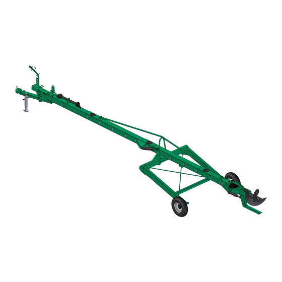
Main view Lagoon Agitator Main view Lagoon Agitator * Reinforcement truss available in option; Draw bar 3 ft longer available in option; Double wheels on lagoon agitator undercarriage available in option. Legend: 1 Propeller 4 Cylinder lock 2 Knife 5 Jack... - Page 18 Main view Lagoon Agitator 4.1.1 Options Legend: 1 Heavy-duty undercarriage 3 Articulated propeller 2 Multipurpose undercarriage 2010-9015-017 18 / 64 04-2015...
-
Page 19: Technical Data
Technical data Undercarriage Technical data Geometric data Lagoon Agitator 32' (9,8 m) 42' (12,8 m) 52' (15,9 m) 62' (18,9 m) 72' (22 m) Agitator length 71'' (1,8 m) Agitator height See undercarriage Agitator width 1765 lbs 2130 lbs 2845 lbs... - Page 20 Technical data Undercarriage Heavy-duty undercarriage Height 91'' (2,31 m) Width (overall) 106'' (2,69 m) Weight 1080 lbs (490 kg) Heavy-duty XL undercarriage Height 91'' (2,31 m) Width (overall) 154'' (3,92 m) Weight 1265 lbs (575 kg) 2010-9015-017 20 / 64 04-2015...
-
Page 21: Tire
Technical data Tractor specifications Multipurpose undercarriage Height 204'' (5,18 m) Width (overall) 157'' (3,98 m) Weight 1850 lbs (840 kg) Tire Tire model Pressure Tire dimensions Weight (inches/mm) (tire without rim) 16.5L X 16.1 26 psi Diameter 31 lbs (1.8 bar) 30.3/770 (14 kg) Width... -
Page 22: Performance Data
Technical data Lubricant specifications Performance data Lagoon Agitator length 32' (9,8 m) 42' (12,8 m) 52' (15,9 m) 62' (18,9 m) 72' (22 m) Maximum 14' (4,3 m) 18' (5,5 m) 22' (6,7 m) 20' (6,1 m) 22' (6,7 m) -
Page 23: Handling And Assembly
Handling and assembly Preparation Handling and assembly Special personnel qualification required for handling Handling must be performed by a qualified forklift operator and/or qualified overhead crane or hoist operator. Installation work must be performed by trained personnel in accordance with the safety instructions. -
Page 24: Packing Material Disposal
Handling and assembly Handling the product and accessories 6.3.2 Installation tools Description Purpose Wrench set To tighten bolts Ratchet tool set To tighten bolts Torque wrench To tighten bolts at specified torque Packing material disposal Handle the packing material properly and dispose according to your local rules and regulations on waste disposal. -
Page 25: Lagoon Agitator Assembly
Handling and assembly Lagoon Agitator assembly Lagoon Agitator assembly Lagoon Agitator split version ● Remove driving shaft protective device (1); ● Place the front agitator section (A) on skids; ● Using a crane, lift the rear agitator section (B) and align it for assembly;... - Page 26 Handling and assembly Lagoon Agitator assembly ● Connect hydraulic hoses on the frame side. Standard, heavy-duty and heavy-duty XL undercarriages ● Fix the hubs to the undercarriage frame, then install the wheels; ● Once undercarriage assembled, lift the agitator over the undercarriage;...
- Page 27 Handling and assembly Lagoon Agitator assembly ● Install the cylinder(s) and the lock cylinder(s) as illustrated hereafter; ● Install the tension arms on both sides of the agitator (HD and HD XL undercarriages). 2010-9015-017 27 / 64 04-2015...
- Page 28 Handling and assembly Lagoon Agitator assembly Multipurpose undercarriage (optional) ● Fix the hubs to the undercarriage frame, then install the wheels; ● Once undercarriage assembled, lift the agitator over the undercarriage; ● Using a brush, apply all purpose grease over the pivot section (7);...
- Page 29 Stabilizing leg (on Lagoon Agitator with standard, heavy-duty and heavy-duty XL undercarriages only) ● Install stabilizing illustrated hereafter. ● At this point, the Lagoon Agitator can stand safely on the ground by adjusting the jack and the stabilizing leg adequately. 2010-9015-017 29 / 64 04-2015...
- Page 30 Handling and assembly Lagoon Agitator assembly Hydraulic hoses support ● Install the support; ● Insert the hydraulic hoses in the rings (9); ● Install the hydraulic connectors in the support (10). 2010-9015-017 30 / 64 04-2015...
-
Page 31: Initial Commissioning
Initial commissioning Initial commissioning Special personnel qualification required for initial commissioning Initial commissioning must be performed by trained personnel in accordance with the safety instructions. Read the section Safety - Personnel qualifications. Safety instructions for initial commissioning Warning! Do not start this product until the initial commissioning checklist is completed. - Page 32 Initial commissioning 7.3.2 Power steering control valve Attention! Since tractors can be equipped with an open or a closed hydraulic system, the control valve must be set with the appropriate plug to avoid overheating/damaging hydraulic components. Contact your tractor dealer. Use the appropriate plug in order to match the tractor hydraulic system: ●...
-
Page 33: Spare Safety Shear Bolts
Initial commissioning Initial commissioning checklist Spare safety shear bolts Remove and save the extra safety shear bolts (4). Shear bolts replacement Tractor PTO Part No. Dimensions Quantity 1⅜''-6 splines 2010-7505-710 ⅜''-16NC x 1 1¾'' - 20 splines 2010-7505-720 ⅜''-16NC x 1 Initial commissioning checklist This checklist must be completed by the dealer and the customer to validate that the product is assembled and/or installed according to the manufacturer's... - Page 34 Initial commissioning Initial commissioning checklist 2010-9015-017 34 / 64 04-2015...
- Page 35 The owner received the instruction manual from the dealer and commits to read it. The owner is instructed by the dealer on how to operate and maintain the product. The Lagoon Agitator is connected to the tractor and secured with safety chains. The safety labels are installed.
- Page 36 Initial commissioning Initial commissioning checklist 2010-9015-017 36 / 64 04-2015...
-
Page 37: Checks After Initial Commissioning
Hand over warranty registration form The warranty registration form must be completed and signed by the customer and the dealer. The warranty registration form must be returned to GEA Farm Technologies Canada Inc. / Division GEA Houle to validate the warranty. -
Page 38: Operating
Operating Checks before operating Operating Special personnel qualification required for operation Operation must be performed by qualified personnel in accordance with the safety instructions. Read the section Safety - Personnel qualifications. Safety instructions for operation Attention! To operate the equipment safely, the tractor operating the equipment must meet the tractor specifications given. -
Page 39: Description Of Controls
Connecting the Lagoon Agitator 8.5.1 Draw bar connection Insert the tractor draw bar in the Lagoon Agitator hitch; Insert a 1'' hitch pin through the draw bar to lock it in place; Order the part No. 2018-3802-420 (1'' hitch pin) if needed;... - Page 40 Operating Connecting the Lagoon Agitator 8.5.2 PTO driveline connection Danger! There is a risk of being crushed between moving and stationary parts. It is strictly forbidden to stand in the danger zone. Turn off the tractor and apply the hand brake before connecting or disconnecting the PTO driveline.
- Page 41 Appendix - Hydraulic diagrams. Connect the Lagoon Agitator hydraulic hoses to the tractor. Double check all connections for safety purpose. Connect the electrical outlet of the Lagoon Agitator to the tractor, if applicable. 2010-9015-017 41 / 64 04-2015...
-
Page 42: Moving The Lagoon Agitator
Operating Moving the Lagoon Agitator Moving the Lagoon Agitator Caution! The hitch, tires, wheels, hubs and axles of the pump are designed for agricultural use only. They are not approved to be towed at any speed above 25 mph (40 km/h). -
Page 43: Positioning The Agitator
Operating Positioning the agitator 8.6.2 Moving the Lagoon Agitator with multipurpose undercarriage Before moving, perform steps in section: Basic preparation steps before moving the agitator. Positioning the agitator 8.7.1 In a lagoon ● Make sure undercarriage cylinder(s) is/are unlocked position;... - Page 44 Operating Positioning the agitator ● Secure the agitator with the stabilizing leg (if applicable). 8.7.2 In a concrete reservoir (using the multipurpose undercarriage only) ● Make sure undercarriage cylinder(s) is/are unlocked position; ● Connect the PTO; ● Swivel the undercarriage for the front wheels to touch the ground; ●...
- Page 45 Operating Positioning the agitator ● Swivel the undercarriage in vertical position; ● Extend the telescopic legs until they touch the bottom of the pit; ● Move the agitator backward; ● Immerse the propeller into the manure; ● Once the agitator is positioned, apply tractor safety brakes. 2010-9015-017 45 / 64 04-2015...
-
Page 46: Agitation Mode
Operating Agitation mode Agitation mode Engage the PTO at minimum RPM; Gradually increase the PTO up to 540 RPM; Once the manure is homogenized, decrease RPM; Stop the PTO; The articulated propeller option makes manure homogenization faster. See the operating mode below. 2010-9015-017 46 / 64 04-2015... -
Page 47: Removing The Agitator
Operating Removing the agitator Removing the agitator From a lagoon ● Stop the PTO; ● Retract the stabilizing leg (if applicable); ● Raise the propeller out of manure; ● Remove tractor safety brakes; ● Move the agitator forward; ● Make sure undercarriage cylinder(s) is/are in locked position;... - Page 48 Operating Removing the agitator ● Move the agitator forward until the front wheels touch the wall; ● Retract the telescopic legs; ● Swivel the undercarriage legs up; ● Move the agitator forward; ● Swivel the undercarriage for the rear wheels to touch the ground; ●...
- Page 49 Operating Removing the agitator ● Install the PTO (1) on transportation support. 2010-9015-017 49 / 64 04-2015...
-
Page 50: Troubleshooting
Troubleshooting Safety instructions for troubleshooting Troubleshooting Special personnel qualification required for troubleshooting Troubleshooting must be performed by trained personnel in accordance with the safety instructions. Read the section Safety - Personnel qualifications. Safety instructions for troubleshooting Warning! HYDRAULIC LINE UNDER PRESSURE! Do not use your fingers to check for leaks. -
Page 51: Troubleshooting Possible Faults
Troubleshooting Troubleshooting possible faults Troubleshooting possible faults Symptom Possible cause Solution Agitator is not agitating Broken PTO shear bolts. Replace PTO shear bolts. properly or not at all. Worn out propeller/knife. Replace part. driveline Inspect the driveline. defective joint disconnected. Broken shaft in driveline. -
Page 52: Maintenance
Maintenance Safety instructions for maintenance Maintenance 10.1 Special personnel qualification required for maintenance work Maintenance work must be performed by trained personnel in accordance with the safety instructions. Read the section Safety - Personnel qualifications. 10.2 Safety instructions for maintenance Danger! There is a risk of being crushed between moving and stationary parts. -
Page 53: Scheduled Maintenance Responsibilities
Maintenance Scheduled maintenance responsibilities 10.3 Scheduled maintenance responsibilities 10.3.1 GEA Farm Technologies Canada Inc. / Division GEA Houle maintenance schedule Task Action by Visual inspection Check oil level in oil bath (optional) Check oil level in oil tank Grease the PTO driveline... -
Page 54: Visual Inspection
Grease the PTO driveline 10.4 Visual inspection Before each working day Inspect the Lagoon Agitator to find any defective part or sign of abnormal wear (loose bolts, clamps, wear on propeller). 10.5 Check oil level in oil bath Before each working day ●... -
Page 55: Grease Driving Shaft Bearings
Maintenance Grease undercarriage pivot points 10.8 Grease driving shaft bearings After each working day and every 10 hours of operation ● Remove the cover; ● Use specified grease or equivalent TRC 880 Crown and Chassis® grade 0 (2010-4300-790); ● Replace the cover; ●... -
Page 56: Grease Bearing Housing
Maintenance Replace propeller knife 10.11 Grease bearing housing After each working day and every 10 hours of operation ● Grease all points where a grease gun label is affixed; ● Use all-purpose grease. 10.12 Clean the equipment After each working day Attention! Use tap water to clean this product. -
Page 57: Decommissioning
Decommissioning Final decommissioning/disposal Decommissioning 11.1 Special personnel qualification required for decommissioning Decommissioning may only be performed by qualified personnel in accordance with the safety instructions. Read the section Safety - Personnel qualifications. 11.2 Safety instructions for decommissioning Attention! Keep all hose couplings clear of dirt and sand when disconnected from the tractor. -
Page 58: Appendix
Appendix Label position Appendix 12.1 Label position 2099-4720-010 2099-4720-020 2010-4701-590 2099-4721-020 2099-4725-100 US / EU US / EU 2003-4701-240 2099-4725-310 US / EU 2010-4703-430 2010-9015-017 58 / 64 04-2015... -
Page 59: Abbreviations
Appendix Abbreviations 12.2 Abbreviations Terms Explanation Terms Explanation Ø diameter European Community clockwise counterclockwise facsimile I.D. inside diameter Inc. Incorporated national coarse O.D. outside diameter power take off polyvinyl chloride Society Automotive Quebec Engineers United States of America World Wide Web Units Explanation Units... -
Page 60: Hydraulic Diagrams
Appendix Hydraulic diagrams 12.3 Hydraulic diagrams 12.3.1 Hydraulic diagram of a Lagoon Agitator with standard undercarriage Option 2010-9015-017 60 / 64 04-2015... - Page 61 Appendix Hydraulic diagrams 12.3.2 Hydraulic diagram of a Lagoon Agitator with heavy-duty undercarriage Option 2010-9015-017 61 / 64 04-2015...
- Page 62 Appendix Hydraulic diagrams 12.3.3 Hydraulic diagram of a Lagoon Agitator with multipurpose undercarriage Option 2010-9015-017 62 / 64 04-2015...
- Page 63 Appendix Hydraulic diagrams 2010-9015-017 63 / 64 04-2015...
- Page 64 Excellence • Passion • Integrity • Responsibility • GEA-versity GEA Group is a global engineering company with multi-billion euro sales and operations in more than 50 countries. Founded in 1881, the company is one of the largest providers of innovative equipment and process technology.
Need help?
Do you have a question about the Lagoon Agitator and is the answer not in the manual?
Questions and answers