Advertisement
Quick Links
©Johnson Outdoors 2021
Do NOT replace the complete i-Pilot as a boxed marine accessory – trouble shoot and replace the defective part!
Connect motor to the voltage appropriate (12/24/36) for the motor being serviced. For Terrova, Riptide Terrova, Ulterra,
Riptide Ulterra, and Ultrex motors the motor must be deployed and the System Ready light "ON" for the motor and
i-Pilot system to function.
Make sure the i-Pilot remote and controller assemblies have the latest software downloaded.
TROUBLESHOOTING
Further information for issues not specific to i-Pilot can be found in the specific model repair manuals.
Part I.
General Troubleshooting
Part II.
Miscellaneous System Information
Part III.
Remote Quick Reference Guide
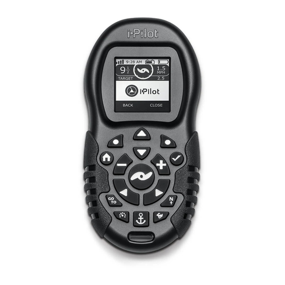
Please note the differences in the following pictures as they will be referenced throughout this
manual. These are referred to as i-Pilot remotes:
Remote for i-Pilot 1.0
p/n 2994085
The i-Pilot controllers are located in the top control box head. This is where the GPS receiver and
compass is housed. Please note the following differences between the controller decals for i-Pilot
versions 1.0, 1.5, and 1.6.
i-Pilot 1.0
i- Pilot Wireless Accessory
Remote for i-Pilot 1.5
p/n 2994170 & p/n 2994171 (Ulterra)
(Ulterra remote has trim/stow/deploy buttons) (Blue Tooth® enabled i-Pilot system)
i-Pilot 1.5
pages 1 through 6
pages 7 through 9
pages 10 through 16
Remote for i-Pilot 1.6
p/n 2994075
i-Pilot 1.6
(Blue Tooth® enabled i-Pilot system)
Advertisement

Subscribe to Our Youtube Channel
Related Manuals for Johnson Outdoors i-Pilot

Summary of Contents for Johnson Outdoors i-Pilot
- Page 1 Pilot Wireless Accessory Do NOT replace the complete i-Pilot as a boxed marine accessory – trouble shoot and replace the defective part! Connect motor to the voltage appropriate (12/24/36) for the motor being serviced. For Terrova, Riptide Terrova, Ulterra, Riptide Ulterra, and Ultrex motors the motor must be deployed and the System Ready light “ON”...
- Page 2 NOTE: On PowerDrive and Riptide PowerDrive (V2 and newer), once the i-Pilot is installed the i-Pilot remote will be the only means of steering the PowerDrive motor. The corded footpedal will no longer steer the motor if the i-Pilot Controller cable is disconnected and the footpedal reconnected.
- Page 3 The i-Pilot 1.0 or 1.5 remote displays an “F” on the LCD screen OR the i- Case XIII. Pilot 1.6 remote displays “Motor Error”. (refer to pictures on first page for remote versions) The screen on the 1.6 remote displays “RF error”.
- Page 4 Step 2. Be sure to keep all ferrous metallic objects away from the i-Pilot Controller as they will have an impact on the built-in compass. Such objects include: anchors, metal framework, etc…...
- Page 5 AutoPilot regardless of the Mode selected. Wait for your GPS signal strength to reach at least one bar, then re- engage AutoPilot. Case V. i-Pilot won’t let me turn on certain features like Advanced AutoPilot, Record, Track to Start/End, or Spot-Lock.
- Page 6 Step 1. Verify you did not accidentally enable another automatic feature such as AutoPilot or Spot-Lock. Step 2. The Arrival Mode may be set to OFF. When the End or Start point of an iTrack is reached the i-Pilot Link will automatically cancel iTrack navigation.
- Page 7 Case XIII. The i-Pilot 1.0 or 1.5 remote displays an “F” on the LCD screen OR the i-Pilot 1.6 remote displays “Motor Error”. Cause: This indicates that the i-Pilot Controller is not able to communicate with the motor control board. This error will not display on PowerDrive motors.
- Page 8 NOTE: This cannot be due to a problem with the motor or the i-Pilot Controller. Step 1. If this is an i-Pilot remote version 1.0, the customer may be misunderstanding the “low battery” icon. This icon is not a gauge showing the voltage left in the battery. It is simply a warning icon.
- Page 9 If the drive housing does turn, proceed to Step 3. Step 3. Test output voltage to the steering motor at the black and white i-Pilot Controller cable wires by connecting a voltmeter to the wires. With proper voltage supplied to the motor send a steering command from the remote.
-
Page 10: Battery Life
REMOTE PAIRING / LEARNING For i-Pilot 1.6 systems: An i-Pilot controller may pair up to 5 remotes. These 5 remotes can be a combination is standard i-Pilot Link remotes and Micro remotes. Any additional remotes can be paired using the following steps. Once the maximum number of remotes have been paired, the controller will start replacing the oldest paired remote in memory with the new remote. -
Page 11: Audio Modes
04/21 For i-Pilot 1.0 & 1.5 systems: A remote can only be learned to one Controller at a time. A Controller can have an unlimited number of remotes learned to it. The top of the Controller has a single learn button to allow additional remotes to be added to the system. - Page 12 04/21 For i-Pilot 1.0 & 1.5 systems: The i-Pilot Controller contains an internal speaker which can be programmed to work in two different audio modes. The speaker is programmed to operate in audio mode 1 from the factory. To enable different audio modes the hold “+”...
- Page 13 ©Johnson Outdoors 2021 i-Pilot rev 04/21 Part III. Remote Quick Reference Guide i-Pilot remote 1.6...
- Page 14 ©Johnson Outdoors 2021 i-Pilot rev 04/21 Quick Reference Guide 1.6...
- Page 15 ©Johnson Outdoors 2021 i-Pilot rev 04/21 Quick Reference Guide 1.6...
- Page 16 ©Johnson Outdoors 2021 i-Pilot rev 04/21 Quick Reference Guide 1.6...
- Page 17 ©Johnson Outdoors 2021 i-Pilot rev 04/21 i-Pilot remote 1.5...
- Page 18 ©Johnson Outdoors 2021 i-Pilot rev 04/21 i-Pilot remote 1.0...
- Page 19 ©Johnson Outdoors 2021 i-Pilot rev 04/21 Quick Reference Guide This refers to both i-Pilot remote 1.5 & 1.0...
Need help?
Do you have a question about the i-Pilot and is the answer not in the manual?
Questions and answers