Table of Contents
Advertisement
Quick Links
Advertisement
Table of Contents

Summary of Contents for KEYLESS KE-350
- Page 1 KE-350 Keyless Entry Access Control System Installation and Operations Manual...
- Page 2 ESSEX ELECTRONICS, INC. KE-350 All rights reserved. No part of this documentation may be reproduced in any form, without prior written consent of Essex Electronics, Inc. Essex Electronics shall not be liable for errors contained in this manual. The information in this document is subject to change without notice. Essex Electronics, Inc.
-
Page 3: Table Of Contents
Table of Contents INTRODUCTION ............................. 1 ............................. 1 VERVIEW ........................... 1 NPUT EQUIREMENTS ........................... 1 UTPUT APABILITIES ............................2 EYPAD PREPARING FOR INSTALLATION......................3 .......................... 3 YSTEM OMPONENTS THE INSTALLATION PROCEDURE....................... 4 ..........................4 EQUIRED OOLS ....................4 REPARE THE EYPAD FOR NSTALLATION ................ -
Page 4: Introduction
Introduction Overview The KE-350 is a powerful yet easy to use single door, stand-alone access control system with audit trail capabilities. The KE-350 can accommodate up to 500 individual Users, each of which is assigned to one of 16 programmable User Groups. Additional features include a 32-day holiday schedule, manual or timed latching capabilities, optional use of Duress Codes and the ability to automatically adjust Daylight Savings Time. -
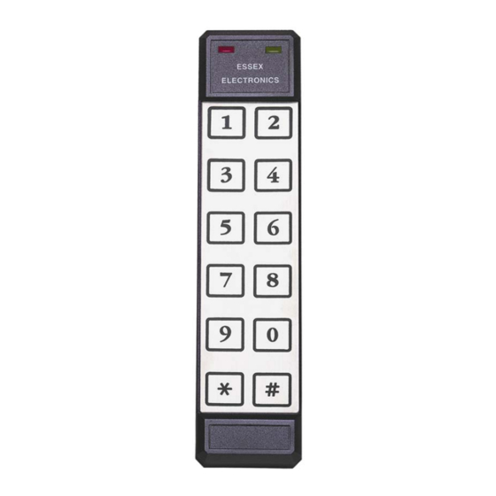
Page 5: The Keypad
Essex Electronics Keypads are designed to perform reliably in even the most extreme environmental conditions. Operating temperatures can range from -40°C to +70°C (-40°F to 160°F). The KE-350 is compatible with any one of the following Keypad styles/configurations: Part Number Matrix Finish/Style... -
Page 6: Preparing For Installation
Relay output via a strike cable (SC). See Appendix A - Typical Wiring Diagrams 5. A Parallel Printer (optional) – connects directly to the KE-350. Although it is not necessary to have a “dedicated” printer, we suggest connecting a printer cable (PC) to the KE-350, which leads to a nearby parallel printer. -
Page 7: The Installation Procedure
KE-350 Installation and Operations Manual The Installation Procedure Required Tools You will need the following tools: 1. Medium sized, Phillips head screwdriver 5. 1/2” (16mm) drill bit 2. 1/8” standard screwdriver 6. 5/32” (4mm) drill bit (For 12-Pad 3x4) 3. Drill 7. -
Page 8: Prepare The Door Jamb For The Electric Strike
KE-350 Installation and Operations Manual Prepare the Door Jamb for the Electric Strike Follow these instructions only if you are using an electric strike to unlock the door. If you are using the main relay to activate a garage door, automatic gate, etc., skip this section. The new electric strike should be checked to verify compatibility with existing door hardware prior to installation. -
Page 9: Install The Control Module
3. Connect 12 to 24 volts to Terminal Strip “B” to screws marked “12-24V AC/DC IN”. Install other Switches There are various options available on the KE-350 as described in the System Programming Section. Most options are built-in and can be controlled through programming. Some options, however, require the installation of either a Door Monitor switch or a Remote Bypass switch. -
Page 10: System Programming Overview
KE-350 Installation and Operations Manual System Programming Overview Once the KE-350 has been installed, the system is ready for programming. Before proceeding with actual programming, we recommend you review the Suggested Initial Programming Steps, System Defaults, System Options and the System Programming Commands &... -
Page 11: System Options
THE MASTER CODE: Knowledge of the Master Code is the highest privilege granted to a user of the KE-350 system. There is only one Master Code, which is used to gain access to all programming areas including System Setup (page 13). Typically only the facilities manager or security director should have access to this code. - Page 12 DAYLIGHT SAVINGS TIME (DST): By default, the KE-350 is configured to automatically adjust the time clock twice each year for daylight savings time. The KE-350 makes the adjustment at 2 a.m. In areas where this adjustment is not necessary, this option can be turned off.
-
Page 13: System Programming Commands & Feedback
Clock to verify the Time, Date and Day of the Week are properly set. User Commands Depending on how the KE-350’s System Options are configured, User Commands are used to operate Manual or Timed Latching and the 2 and 3 Relays. -
Page 14: System Programming
KE-350 Installation and Operations Manual System Programming Programming Individual Users (Add, Modify, Delete or Temporary Users) Authorized users (master code holder or any user assigned to a User Group given the authorization to program users) can program users directly from the keypad. Each Individual User is assigned to one of the 16 User Groups. - Page 15 KE-350 Installation and Operations Manual Programming Individual Users (continued) Keypad Status after Step Completion Step Beep Red LED Green LED Deleting a User by User ID a) To delete a user by User ID, enter 3 # Double Slow Flash...
-
Page 16: Programming System Setup
KE-350 Installation and Operations Manual Programming System Setup The KE-350 System Setup can only be modified by the Master Code holder. When the system is initially setup, the default system settings should be reviewed and necessary modifications should be made prior to other programming. - Page 17 KE-350 Installation and Operations Manual Programming System Setup (continued) Keypad Status after Step Completion Step Beep Red LED Green LED Using Duress Codes (Default: OFF) a) Enter 4 # Double Slow Flash Slow Flash b) Enter 0 # to turn OFF use of Duress Codes...
- Page 18 KE-350 Installation and Operations Manual Programming System Setup (continued) Keypad Status after Step Completion Step Beep Red LED Green LED Configuring 3 Relay (Default: CCTV 30 sec) Double Slow Flash Slow Flash a) Enter 6 # b) Select the desired configuration:...
-
Page 19: Programming The Holiday Schedule
KE-350 Installation and Operations Manual Programming the Holiday Schedule The KE-350 provides a 32 day holiday schedule. Any authorized user can program up to 32 dates (month/day). Each User Group is programmed to either authorize or prevent access during these scheduled dates. -
Page 20: Programming The Time Clock
Programming the Time Clock Authorized users (master code holder or any user assigned to a User Group given the authorization to program users) can program the KE-350’s time clock from the keypad. If the time clock requires adjustment, follow these... -
Page 21: Audit Trail Setup & Printing Audit Transactions
KE-350 Installation and Operations Manual Audit Trail Setup & Printing Audit Transactions The KE-350 logs the last 750 audit transactions. These transactions will remain in memory even in the event of a power interruption. Any authorized user (master code or any user assigned to a User Group given the authorization to program users) can retrieve Audit Transactions from a connected printer. -
Page 22: User Groups
KE-350 Installation and Operations Manual User Groups The KE-350 simplifies the process of programming users by providing 16 programmable User Groups. Rather than assigning authorization options (i.e. latching, user programming and time zone authorization) to each individual user, these authorizations are determined for each User Group. -
Page 23: Modifying User Groups
KE-350 Installation and Operations Manual Modifying User Groups Enter Enter the Master Code or an authorized user code, followed by # Red LED Green LED Example: 9 123 # Slow Flash Solid This opens programming and causes To Print authorizations for a User Group, proceed to step 6. - Page 24 KE-350 Installation and Operations Manual Modifying User Groups (continued) Keypad Status after Step Completion Step Beep Red LED Green LED Program a Temporary Code Authorization Triple Slow Flash Slow Flash a) Enter 4 0 # to prevent Temp Code PGM...
- Page 25 KE-350 Installation and Operations Manual Modifying User Groups (continued) Keypad Status after Step Completion Step Beep Red LED Green LED Printing User Group(s) Double Slow Flash Slow Flash a) Enter 9 # Triple Slow Flash Solid b) To print a specific User Group, enter the...
-
Page 26: Typical Wiring Diagrams - Figurea
KE-350 Installation and Operations Manual Appendix A Typical Wiring Diagrams – Figure A... -
Page 27: Typical Wiring Diagrams - Figureb
KE-350 Installation and Operations Manual Typical Wiring Diagrams – Figure B... - Page 28 KE-350 Installation and Operations Manual Appendix B Individual User Programming Worksheet User ID User Name User Code/PIN User Group (1-499) (3 to 8 Digits) (01-16)
-
Page 29: Individual User Programming Worksheet
KE-350 Installation and Operations Manual Appendix C User Group Programming Worksheet User Days of Times of Latch Temp Delete Relay Relay Holiday Group Entry Entry User User User Access...
Need help?
Do you have a question about the KE-350 and is the answer not in the manual?
Questions and answers