Table of Contents
Advertisement
Quick Links
S
GO G
T
C
S
TAR
O
O
ONTROL
YSTEM
USER MANUAL
Version 4.1.2, February 2020 by Mauro Ghiri
All the pictures and contents here included are property of AVALON INSTRUMENTS. The contents may
not be
reproduced, published, copied or transmitted in any way, including the internet, without the written permission
of AVALON INSTRUMENTS.
Advertisement
Table of Contents

Related Manuals for Avalon Instruments STARGO GOTO

Summary of Contents for Avalon Instruments STARGO GOTO
- Page 1 USER MANUAL Version 4.1.2, February 2020 by Mauro Ghiri All the pictures and contents here included are property of AVALON INSTRUMENTS. The contents may not be reproduced, published, copied or transmitted in any way, including the internet, without the written permission...
- Page 2 Preface Avalon Instruments manufactures astronomical mounts and control systems that are known for excellence of design, superior engineering and extreme accuracy. The StarGo Control System has been designed for integrated use with the Avalon Linear and M-uno mounts, or in a separate control box for the M-zero mount.
-
Page 3: Table Of Contents
Summary 1. System Description and Technical Specifications..............5 1.1 Technical Specifications:....................9 1.2 The StarGO Goto Control System hardware interface..........10 1.3 StarGO Power On......................12 2. StarGo software suite installation..................14 2.1 Mount preliminary settings for a mount quick use with StarGO Software....22 3. StarGO software description.....................25 3.1 Graphic User Interface (GUI)..................25... - Page 4 A2.6 Image management....................77 A2.7 POLAR ALIGNMENT TOOL..................78 A2.8 TIPS & TROUBLESHOOTING.................79 B.1 Software Updating......................80 B.2 Firmware Updating – StarGOLoader................81 ____________________________________________________________________ All Rights reserved...
-
Page 5: System Description And Technical Specifications
Windows 7/8/10 (via ASCOM Driver) and OS X (LX200 classic). The StarGo Goto Control System was designed mainly for the Avalon Instruments mounts but, thanks to the programmable gear ratio and the motors kit available, it can be easily adapted to other mounts also. - Page 6 ____________________________________________________________________ All Rights reserved...
- Page 7 The StarGO Goto Control System is composed by the following parts: 1. The StarGO Control Box, which can be embedded within the mount as in the Avalon Linear and M-Uno, or in a separate control box for the M-Zero. In addition,...
- Page 8 4. The StarGO-BT application for Android devices allows them to interface with the StarGO control box via Bluetooth connection. With this application the Android devices become perfect smart-device control pads. This application, as well as StarGO, is under continuous development to add new functionalities. 5.
-
Page 9: Technical Specifications
Technical Specifications: Computerized control system based on stepper motor technology and General dual communication (USB and Bluetooth or Wi-Fi). Operational Mode Equatorial or Azimuth (for the appropriate mounts) • Single star • Pointing Model Three star (only in Alt Az axis mode) •... -
Page 10: The Stargo Goto Control System Hardware Interface
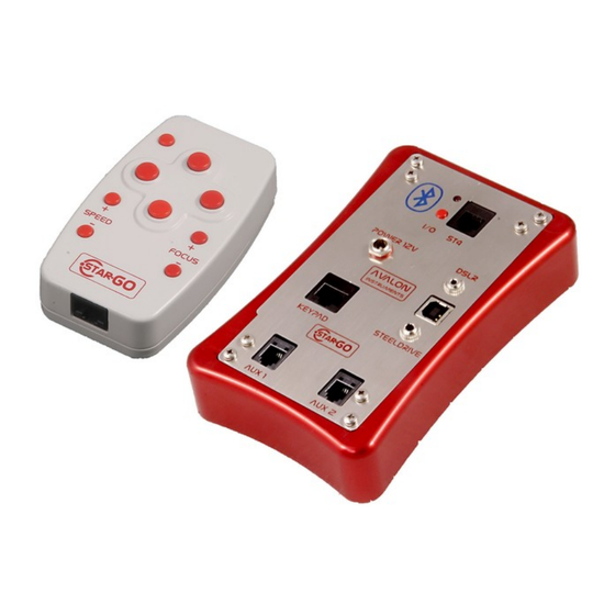
A foam-lined high-impact carrying case for all of the above (provided only with the StarGo Stand Alone kit.) The Main Board for the Avalon Instruments Linear and M-uno mounts comes already internally installed in those mounts from the factory. On the M-zero mount and the Stand Alone kit, it is mounted externally in a separate case. - Page 11 Figure 1.1.b.StarGO Wi-Fi Front Panel On/Off Power button ST4 autoguide port 12-18 VDC power supply plug WiFi capability symbol DSLR Canon exposure management port USB2 I/O Port Handheld keypad RJ45 plug Stepper Motor Auxiliary Output Port (Aux 1) Stepper Motor Auxiliary Output Port (Aux 2) On/Off LED Figure 1.1.c Illustrates the manual keypad which is connected to the StarGo Control Box at...
-
Page 12: Stargo Power On
AUX1 and AUX2. By keeping pressure on the Fn key then pressing the FOCUS- key the selection order is inverted: AUX2, AUX1, Steeldrive (in the Bluetooth version only). By holding pressure on the Fn key and then pressing the S key, each time the S key is pressed, the system speed varies in the order: Sidereal, Solar, Lunar, Terrestrial. - Page 13 Figure 1.3b: StarGO power connection Detailed info about the StarGO power supply using and characterisitics please visit StarGO power supply using web page. ____________________________________________________________________ All Rights reserved...
-
Page 14: Stargo Software Suite Installation
2. StarGo software suite installation In order to get the maximum performances with the StarGO System it is necessary to install the StarGO Software Suite. The installer file can be found in the Installer-Tutorial- Software folder inside the flash drive that comes with the mount. Figure 2.a: StarGo Installer folder location The step by step Windows version installation procedure (that you can also find in a tutorial video on our... - Page 15 Figure 2.b: Installer must be ran as administrator During the software installation process, as described below, the Avalon ASCOM driver, the serial-USB FTDI drivers, the StarGO application, its firmware and related update utility are installed. More details about the StarGo using with others astronomical software can be found in the “SW&StarGO_Tutorial_v1.x.x_eng.pdf”...
- Page 16 2. Select the preferred language and then press OK: Figure 2.c: Installation language chooser 3. The installation splash screen will appear containing the StarGO GoTo Control System Setup Wizard welcome window. Click Next: Figure 2.d: StarGO System setup wizard 4. The welcome window inside the splash screen will be replaced by the License Agreement window.
- Page 17 Figure 2.e: StarGo software license agreement 5. The next window will allow the creation of a StarGO desktop icon. It is advised to accept and then press “Next” Figure 2.f: Desktop icon creation option 6. The next window inside the splash screen will present the summary of the task selected and proposes to start the installation.
- Page 18 Figure 2.g: Start installation window 7. At the end of the installation process a window will be presented to asking to finish the StarGO installation process. It will ask to perform additional operations if needed, such as install the FTDI USB drivers, install the most updated StarGO ASCOM driver and launch the StarGO software at the end of the installation process.
- Page 19 Figure 2.i: FTDI Driver extracting window 9. At the end of the FTDI drivers extraction the “Device Driver Installation Wizard” will appear. Click on the "Next >" button to go on with the installation. Figure 2. j: FTDI Device Driver Installation Wizard 10.
- Page 20 Figure 2.k: driver license agreement 11. Click on “Next”. The windows announcing the correct driver installation will appear. Press “Finish” to exit. The new drivers are ready for the USB connection. Figure 2.l: FTDI finish installation window 12. After the FTDI driver installation (if selected) the Accept the License Agreement in the following window and click on “Next”.
- Page 21 Figure 2.n: Avalon ASCOM driver License Agreement (2) Figure 2.m: Avalon ASCOM driver License Agreement 13. A final window will inform that the installation process has been successfully completed and will propose to view the contained Readme file of the installation. Figure 2.o: Avalon ASCOM final installation message window NOTE: After the installation, to guarantee the contemporary access of all astronomical...
-
Page 22: Mount Preliminary Settings For A Mount Quick Use With Stargo Software
Figure 2.q: Enabling Run as administrator option Figure 2.p: Properties tab selection NOTE: If administrator privileges will not be given, the software will not be able to communicate with the ASCOM driver. 2.1 Mount preliminary settings for a mount quick use with StarGO Software 1) Point the telescope toward the North Pole if you are on the Morthern Emisphere or to Southern Pole if you are on the Southern Emisphere... - Page 23 When you plug in the power connector in to the StarGO board it starts and the led begins to blink but the RA and DEC motors are not yet powered on Once the power has been provided the StarGO is powered but the RA and DEC motors are not yet powered.
- Page 24 Figure 2.1.b: Choose the preferred pointing system 7) Press the Sync Home Position button to align the mount to the Sky (detailed instruction at section 4.5 for Eq mode, 4.6 for Alt-Az mode). At this point you can start with a fine star alignment (1 star or up to 24 star). For detailed GUI instruction please skip to section 3.
-
Page 25: Stargo Software Description
3. StarGO software description Graphic User Interface (GUI) When using StarGo with a computer or other device, activate the StarGO GUI by clicking icon created on the desktop during the program installation. The user interface appearance is shown in Figure 3.1 a. -
Page 26: Parameter Setting
Figure 3.1.c:. Main Panel with the mount unparked A quick click on the LED or on one of the directional arrow buttons will activate sidereal tracking and the LED will remain on (same as the physical LED on the StarGO) producing the same result as briefly pressing the physical button #1 on the StarGO Control Box. - Page 27 Figure 3.2.1a. “SYSTEM” Panel This panel also reports the StarGO software, firmware and ASCOM driver versions as well as the type of mount and the axis mode (equatorial or alt-azimuth). The timeliness of the given versions of firmware and software is evaluated by the software itself and, if they are not current, the user is warned and advised to update.
-
Page 28: Ra Dec Panel
The Bluetooth capability can be switched ON by selecting the checkbox located beneath the SAVE/LOAD buttons. 3.2.2 RA DEC Panel Pressing the RA-DEC tab opens the panel shown in Figure 3.2.2 a which enables access to the guide settings of the mount. Figure 3.2.2.a. - Page 29 Selecting the “Show ALTAZ Coords” check-box will cause the main display to show Alt-Az coordinates instead of Equatorial coordinates. The “Force Meridian Flip” allows a Meridian Flip to be performed before the Meridian is reached. The “Disable Meridian Flip” feature allows to disable the Meridian Flip on both the side of the Meridian, these are the procedures to perform starting from a Sync Home Position to activate the feature: Target on Eastern side, mount pointed to East ( Standard condition, DEC arm down )
-
Page 30: Aux Panel
The procedures can also be used after the Sync Home Position, simply starting from point 3.2.3 AUX Panel Figure 3.2.3.a. “AUX” Panel Clicking on the “AUX” tab brings up a panel (Figure 3.2.3.a) that controls the setting of one auxiliary port dedicated to a Baader Steeldrive focuser (for StarGO Bluetooth version only) and the two AUX 1 and 2 ports controllable by the StarGO. -
Page 31: Advanced Panel
Figures 3.2.3 b , show the main panel appearance when the DSLR and Steeldrive buttons are checked, F igure 3.2.3 c, shows the main panel when are unchecked. The Check for AUX Advanced Function push button allows, when pressed, to access the controls of AUX1 and AUX 2 device motor parameters for fine tuning: NOTE: The motors driven by the AUX 1 and AUX 2 ports are disconnected from the power once they reach the required position. -
Page 32: Align Panel
NOTE: When using the Stand Alone kit on third party mounts, please use the specific mount configuration file that comes with the installer. In the ADVANCED panel, the “REVERSE MOTOR DIRECTION” frame checks allow the inversion of the motor rotation direction if it happens that one or both the mount axes are moving in the wrong direction. - Page 33 The left frame of the ALIGN panel (“OBSERVATORY LOCATION”) allows up to eight observation sites to be set and saved by inserting their geographical coordinates (Latitude and Longitude). NOTE: To operate the mount in Alt-Azimuth mode (for the mounts that allow this operating mode) it is normally sufficient to use a smartphone or tablet equipped with suitable software such as SkySafari (see the following sections 4 and 5), along with to the control keypad.
-
Page 34: Warning Descriptions
StarGO Control Box and the software being used. This can occur quite frequently because both these elements are continuously improved by Avalon Instruments. That is why we repeatedly suggest checking to see if new firmware and software updates are available. New versions are regularly distributed through Support page of the Avalon web site. -
Page 35: Using The Special Features Of The Main Graphical Area
Figure 3.3.b: Motor torque warning message Increasing the motor torque beyond recommended limits could potentially cause damage and dangerous over-heating of the motors and associated hardware. For that reason it is advisable to remain below the specified threshold. Pressing the "OK" button will cause the StarGO to be restarted, with the loss of all operations in progress (Figure 3.3.b The last alarm is generated in the SYSTEM panel. - Page 36 Figure 3.4a: Main Graphical Area The information given are applicable to both equatorial and alt-azimuth modes. The large window on the Figure 3.4b. RA and DEC coordinates upper left ( Figure 3.4b shows the current values of Right Ascension RA and Declination DEC coordinates of the telescope.
- Page 37 On the top right there are three buttons, by clicking the first on the left the "Virtual Keypad" will appear, a small panel always on top screen very useful to control the mount with third party Software as "Carte du ciel", "Stellarium" etc. The Virtual Keypad panel allows to easily control and move the mount with the StarGo software functions also when you are using third party softwares.
- Page 38 proper cable for that camera. Activate the DSRL function by pressing the button with the same name in the Main GUI. Figure 3.4.g: DSLR button Currently, this port supports only Canon and some Sony DSLRs. Use the Aux ports for cameras of other brands.
- Page 39 The total time in seconds is reported in the window in the upper left corner. The “Start” button initiates the sequence of the exposures. The “Stop” button interrupts the sequence before the total number of shots is carried out. The “Resume” button re-starts a sequence that has been previously interrupted. The “Shot”...
- Page 40 In this window it is possible to insert new names for the device connected to each of the Aux ports. This name will appear in the above matrix. Also the gauge units defined in the AUX Tab will be reported in the matrix for each device. In the following example the “Steeldrive”...
-
Page 41: Sections
Double clicking on the small GoTo buttons in the table will move the device to the chosen position. The values of the Posiz. column are manually introduced, corresponding to a well defined position. Use of the StarGO for controlling telescope in Equatorial Mode NOTE: The instructions reported in this section are applicable only to the Equatorial operating mode. - Page 42 to the StarGO (see Appendix, section A2.3), every Sync operation performed after the restart contributes to build the model. For example, if during an observing section, a certain number “n” of Syncs is performed, a n/24 model is progressively built. If a new model or an existing one has been loaded in memory, each additional Sync will increase the number of stars of the model up to the total of 24.
-
Page 43: Use Of The Stargo With A Pc For Controlling Telescope In Alt-Az Mode
telescope eyepiece to bring the star exactly to the center in field of view. Once the star is perfectly centered, press the SYNC icon in the CDC menu. The telescope is now aligned with the sky. This operation can be considered as a “single star alignment”. -
Page 44: Mount Control Using Ascom Driver
Mount control using ASCOM driver As previously mentioned, the StarGO system is compatible with the ASCOM astronomical standard via the Avalon ASCOM driver that Avalon Instruments has developed and distributed for use with its proprietary StarGO system. This capability makes it possible to manage the mount using third party software (i.e. - Page 45 Figure 3.7a: CdC main GUI_1 The “General” panel will open. Select the ASCOM button, as illustrated in the following Figure 3. 7b , and click OK. Figure 3.7.b. CdC Telescope Interface selection window Open the Control Panel clicking on the icon highlighted with the green oval in Figure 3.
- Page 46 Figure 3.7.c: CdC Main GUI_2 On the ASCOM panel below (Figure 28) chose the ASCOM driver by clicking on “Select” button. Figure 3.7.d: ASCOM telescope interface The classic “ASCOM Telescope Chooser” panel will open. Select AvalonStarGo.NET driver in the dropdown menu and then click “OK”. ____________________________________________________________________ All Rights reserved...
-
Page 47: Using The Stargo With A Wireless Connection
Figure 3.7e: ASCOM Telescope Chooser Once the Avalon ASCOM driver has been accepted, press the “Connect” button on the ASCOM telescope interface panel of Figure 3. 7e At this point the telescope will be under ASCOM control and it may be driven by CdC as well as other ASCOM compatible programs like Astrotortilla, PHD Guiding or Sequence Generator Pro (SGP), for example. -
Page 48: Bluetooth Pairing The Stargo With A Windows Pc
Avalon Instruments will add more Device/Software combinations once further compatibility tests, now being conducted, have been successfully completed. The use of TheSkyX Pro and Sky Safari Pro also makes the Avalon Instruments mounts operable n the Mac Operating System (MACOSX). - Page 49 Figure 3.8.1b: Choose StarGo device In this panel select the Bluetooth item and then the StarGO device. In our example it is named M-zero. However other Avalon Instruments product names are possible and are easily identificable. A subpanel will open: Figure 3.8.1c: Insert pincode...
-
Page 50: Bluetooth Pairing The Stargo With A Macintosh
3.8.2 Bluetooth pairing the StarGO with a Macintosh The procedure to pair a Mac with the StarGO via Bluetooth is very similar to that described above. On the Mac follow these steps: Open System Preference window and select Bluetooth. The following panel will open: Figure 3.8.2a: StarGo Bluetooth pairing with Mac The devices already connected will be shown in the window and the rotating wheel in the upper right side will indicate that the Mac is searching other available devices. -
Page 51: Connect The Stargo To A Windows Pc Via Wifi
Figure 3.8.2c Insert pincode Enter the StarGO code, which is normally 1234. If it is different, the correct code will be provided with StarGO documentation. After few seconds the pairing will be established as shown in this screenshot: Figure 3.8.2.d: StarGo connected The Mac is now connected to the StarGO. -
Page 52: Connect The Stargo To A Macintosh Via Wifi
Type “avalon1234” or whatever password Avalon Instruments has provided with the software. Wait few seconds until the connection is established. The StarGO SW is now wirelessly connected to the PC and the mount is ready to be operated. -
Page 53: Stargo And Skysafari
4. StarGO and SkySafari The StarGO Control System may be easily operated by the SkySafari application running on Macintosh computers and Android and iOS based tablets and smartphones. As described earlier, Apple mobile devices (iPad and iPhone) can be connected only via WiFi, whereas Android devices can be connected with both Bluetooth and WiFi. - Page 54 Then press "StarGo_xxx" (where xxx represents the StarGo serial number) Figure 4.1.1.b: StarGO net selection After a few seconds a small window will require the pairing PIN: Figure 4.1.1.c: Bluetooth pairing window Enter the PIN provided by Avalon (usually 1234) and press OK. After few seconds the device will be paired (see next screenshot) with the StarGO.
-
Page 55: Wi-Fi Connection Of Stargo With An Android Tablet Or Smartphone
Figure 4.1.1d: StarGO connected screenshot 4.1.2 Wi-Fi connection of StarGO with an Android tablet or smartphone This operation can be easily done following these simple steps (the figures can be slightly different in various Android devices): Figure 4.1.1e: Android Wi- Fi selection network Select Setting in the device main screen and, when window opens, select Wi-Fi in “Wireless and network”... - Page 56 Figure 4.1.1f: StarGO network password entering windows At the first connection, a password is required. Type “avalon1234” or whatever password Avalon Instruments has provided with the software. After few seconds the connection is established as shown in the picutre below.
-
Page 57: Sky Safari Setup
Sky Safari setup Before using SkySafari with Avalon mounts it is necessary to set some important parameters in the program setup page. SkySafari is provided with numerous parameters to be set, mostly dedicated to the program display characteristics. This section of the manual will deal only with those parameters which are necessary for the Avalon mount control. - Page 58 4. Check the correct axis mode is settings Figure 4.3.b: Set the correct mount Axis Mod 5. Set the correct Observatory Location Figure 4.3.c: Set the correct Observatory Location ____________________________________________________________________ All Rights reserved...
- Page 59 6. On the Align panel choose the preferred pointing system (SINGLE STAR, 3 STAR, MULTISTAR) Figure 4.3.d: Choose the preferred pointing system 7. Close the StarGO software, remove the power supply connector from the StarGO control unit. Lastly, disconnect the USB cable from the StarGO control unit. Now the mount is ready to work with a device using SkySafari without the need of a pc.
- Page 60 Press the Settings icon on the bottom bar. A screen will appear with a long list of all the parameters to be set. First, open the “Time and Date Setting” arriving at the screen shown below. If the device date and time shown on the screen are correct, check the “Use current Time”...
- Page 61 The last but very important set of parameters is the “Scope Setup Settings”. The instructions in this page show how to insert the telescope and mount type (Meade LX-200 Classic and Equatorial GOTO or Alt-Az as needed, respectively). Figure 4.3h: SkySafari communication settings panel In case of a Macintosh and iOS device connection via Wi-Fi, an IP Address of 10.0.0.1 and a Port Number 4030 should be entered as shown in the following screenshot:...
- Page 62 NOTE: “Set Time and Location” option inside the Scope Setup settings. When the Site & Location checkbox is activated, Skysafari send, during the connection with the StarGo, the data about the time and the location in order to update the internal StarGo location.
-
Page 63: Skysafari Connection And Alignment
SkySafari Connection and alignment Once all the operations described in the previous sections have been completed, it is possible to start moving the telescope using SkySafari. a. Eq mode: The first action to perform for the mount in Equatorial Mode is to manually put the telescope in the “Home”... - Page 64 “Sync Home Position” using the StarGO software as described in section 3.2.5 and will transmit the point where the mount is really pointing at that moment (i.e. the Celestial Pole) to the StarGO. NOTE: When the “Multi Star” is checked in the StarGO (see section 3.2.5, F ig ure .
- Page 65 Figure 4.4d. Sync on southern horizon The second phase in this sequence is the choice of any star very near to the Meridian and to the Southern horizon. In this case the star is η Aql (see ovals 3 and 4 of figure 4.4d). Note that the telescope is still in the initial position (oval 5). Again it is possible to see a small difference in RA from the point 0,0 due to the time lapse.
- Page 66 Now the telescope can be operated using the available commands and the direction control on the side of SkySafari screen below. On the left the RA direction controls and on the right the DEC controls. The telescope movement rate can be adjusted using the yellow “Rate” slide bar above the telescope controls.
-
Page 67: Mount Control With Stargo-Bt For Android
Application Installation The app is contained in a single file named StarGo-BT.x.y.z.apk, where x.y.z represent the software version. This program, like all other Avalon Instruments, software, drivers and related manuals, are continuously improved and increased in functionality. Thus, the version numbers will vary quite often. -
Page 68: Application Use
When the file is selected, the app installation process will start. It is very probable that, at the start of this process, the installer will inform you that it is not possible to continue because the installation of applications not coming from the Play Store is not allowed. To continue it will be necessary to open the Setup Window of the device and (at least temporarily) enable the installation of applications from unknown sources under the option “Unknown Sources”... - Page 69 Once the connection is established, the app will show the main screen through which all the control operations on the StarGO can be performed. The screen slides vertically to allow the access to the various setup functions The application screen looks familiar because it is dominated by the same directional keys and the central STOP key that have equivalent functions of the StarGO software keys.
-
Page 70: Application Setup
Application setup Next, the screen will be replaced with a group of command setting labels for controlling the mount in Bluetooth: Figure 5.3.a: StarGO BT Tracking speed The first of the available commands is the “TRACKING SPEED” label (Figure 5.3.a). Touching the label opens a string of buttons used to select the desired tracking speed: Sidereal, Solar, Moon and Earth. - Page 71 Figure 5.3.b: StarGO BT Aux1 Figure 5.3.c: StarGO BT Aux 2 Figure 5.3.d: StarGO BT app By touching the “MOUNT SETTING” (Fig. 5.3e) label brings up a set of commands to reverse the motion direction of the RA and/or the DEC motors, to chose among the M-zero, Figure 5.3e: StarGO BT mount setting ____________________________________________________________________...
- Page 72 M-uno and Linear mounts, and to select the operational mode between Alt-Azimuth and Equatorial (GEM). The middle label, “SITE POSITION,” (Fig. 5.3f) will bring up a set of commands to introduce the observation site coordinates and to show their values. The commands are self explanatory.
-
Page 73: A1.0 Introduction
APPENDIX X-SOLVER TOOL Plate Solve and Sky Modelling A1.0 Introduction After StarGO Version 5.1.42, the Software Suite includes the X-Solver, which is an application based on the Plate Solve solution. With X-Solver it is possible to build a Sky Model allowing up to 24 stars to be saved and used later during other night sessions. The X-Solver application comes with two very useful tools: the Sky Model and Polar alignment. -
Page 74: A2.0 X-Solver Operation
A2.0 X-Solver Operation A2.1 X-Solver connection The Figure A2.1a shows the first window that appear after double clicking on the X-Solver icon located on the desktop. Figure A2.1a: GUI before connecting to X-Solver Once the X-solver window is opened, the top header will inform the user about the program version and which Plate Solver solution method will be used. - Page 75 Figure A.2.1b: Equipment connection panel Note that the StarGO is automatically connected if it, as recommended, has been corrected switched on and connected before the X-Solver launch. The first operation to be performed is to choose the CCD by clicking over the “CAMERA CHOOSER”...
-
Page 76: A2.2 - Settings Panel
After the connection a new frame will appear on the right side of the main X-Solver windows with two tabs: Plate Solve and Settings. Figure A.2.1e: X-Solver connected A2.2 – Settings panel First select the desired plate solving method from the available choices: ... -
Page 77: A2.3 Plate Solve Panel
A2.3 Plate Solve panel This Panel enables the acquisition and solving functions by selecting the following parameters. The left frame of Fig. A2.3 is related to the plate solving of an existing image whereas the right one is related to an online zquisition of the image. Exposure: Set a test starting time from 5 sec to 10 sec. -
Page 78: A2.4 The X-Solver As Single Star Plate Solver
A2.4 The X-solver as single star Plate Solver To take an image press the SHOT button on top main menù. The LIVE VIEW button allows continuous shooting. The X-Solver may also be used to perform a Single Star alignment even if telescope is pointing to an unknown part of the sky. - Page 79 To simplify the sky point choice it is possible to automatically generate points using one of the three buttons on the menu ( 3+3, 5+5, 8+8) and, eventually, manually complete the point generation up to 24 positions. After the scheme has been completed, we are able to build a personalized model of the sky by performing the following operations: 1.
-
Page 80: A2.6 Image Management
A2.6 Image management Some of the commands in the top menù are useful AIDS to PERFOM a preliminary focusing, to manage the image itself and to optimize target framing. Figure A2.6a: X-Solver top menu string The first commands of the string have been already described in the previous sections. The second button allows to take a single imagine to work with. -
Page 81: A2.7 Polar Alignment Tool
Figure A2.4.c: X-Solver zoom tool The desired magnifying ratio can be adjusted by clicking on the appropriate buttons on top. A2.7 POLAR ALIGNMENT TOOL A precise and fast Polar Alignment of the mount can be performed using the plate solving. This process is iniziated by clicking on the P. -
Page 82: A2.8 Tips & Troubleshooting
The fraction of turn to be applied may be calculated dividing the values of the errors provided by the X-Solver by the number of the table for each avalon mount. A2.8 TIPS & TROUBLESHOOTING THE AVALON INSTRUMENTS Support web page provides information and suggestions on installation and troubleshooting. -
Page 83: Software Updating
B.1 Software Updating The StarGO software and firmware are subject to continuous improvement and updating, with additional functions being added all the time. We therefore advise users to frequently consult the Avalon Instruments website Support page to be assured that their StarGO software and firmware are the latest updated versions. -
Page 84: Firmware Updating - Stargoloader
StarGO Loader application window to open, as below: Figure B.2a: Firmware Upgrading loading window NOTE: Avalon Instruments provides the firmware to be installed pre-set with generic parameters so that the existing settings will not be lost. For that reason, it is recommended to save the “Mount Configuration File”... - Page 85 2. Choose the most recently updated file with .af2 extension among those shown in the window. Press Open to confirm. The StarGo loader window will show the name of the chosen file. Verify that it is correct and then press Start to begin the uploading process.
- Page 86 Figure B2e: StarGO Firmware Upgrading bar window 5. When the process is completed, the successful uploading is announced. Press Close button to exit the application. Figure B2f: StarGO Firmware upgrading completed 6. Restart StarGO and connect it. A warning will appear informing that the mount is not configured asking to reload the Mount Configuration File previously saved: 7.
- Page 87 Figure B.2.g: StarGO Misconfiguration Warning Figure B.2.h: StarGO Mount Configuration File selecting ____________________________________________________________________ All Rights reserved...
- Page 88 8. Choose the correct configuration file. When loading is finished, the StarGO will be ready to work with the newly installed firmware and the correct configuration, NOTE: The uploader is able to restart its function, even after an accidental interruption of the uploading process, without any risk of StarGO hardware damage. In this case the led does not blink, simply restart the operations from the beginning.
Need help?
Do you have a question about the STARGO GOTO and is the answer not in the manual?
Questions and answers