
Summary of Contents for ACDC PAPILLON250
- Page 1 PAPILLON250 User Manual ARTICULATED ARM OPENERS 24V DC GEAR MOTOR FOR RESIDENTIAL USER MANUAL...
-
Page 2: Table Of Contents
INDEX 1.2 Installation 1.2.1 Standard Installation 1.2.2 Dimension Chart 1.2.3 Components of Installation 1.2.4 Installation of Articulated Arm Opener 1.2.5 Emergency Release 1.2.6 WIFI Device 1.2.7 Photocells 1.2.8 Power Supply Connections 2.1 Wiring Connection 2.1.1 Master Motor is installed at right side 2.1.2 Master Motor is installed at left side 3. -
Page 3: Installation
1.2 Installation 1.2.1 Standard Installation 2x1.5 mm 4x0.5 mm RX - 4x0.5 mm TX - 4x0.5 mm 2x1.5 mm 2x1.5 mm 1. 24V DC blinker with integrated antenna 2. Push Button 3. Photocells 4. 24V DC articulated arm opener 5. TM3 Transmitter 1.2.2 Dimension Chart Please comply with the measures shown on the chart for Inward Opening... -
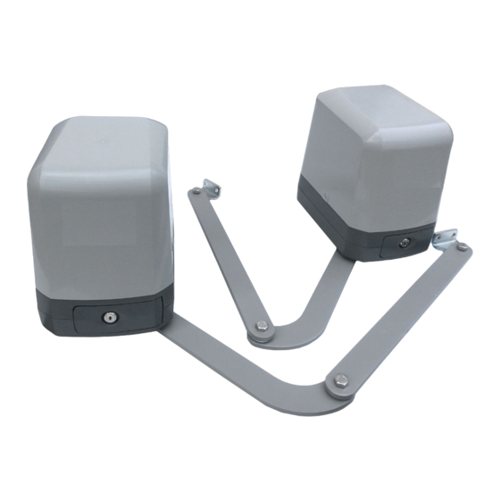
Page 4: Components Of Installation
Straight arm 1 pce 1.2.3 Components of Installation Curved arm 1 pce U-shaped fixing plate 1 pce Mechanical stopper 2 pcs Front-end fixing bracket 1 pce Screw 4 pcs Nut Ø10 2 pcs Screw 2 pcs Gasket 2 pcs Screw 2 pcs Spring washer 4 pcs... -
Page 5: Emergency Release
5) Closed position adjustment : 5.1 After the full closed position decided, fix the corresponding mechanical stopper at the position. 5.2 After the full closed position decided, make the pointer on limit switch aligned with the pointer on the curved arm. (Red points shown on the figure below indicate the pointers) 6) Opened position adjustment : 6.1 Adjust the gate to full opened position and after the position decided, fixe with corresponding mechanical stopper. -
Page 6: Photocells
1.2.7 Photocells The safety photocells are security devices for control automatic gates. Consist of one transmitter and one receiver based in waterproof covers; it is triggered while breaking the path of the beams. SPECIFICATION: Detection Method Through Beam Sensing Range MAX~15m Input Voltage AC/DC 12~24V... -
Page 7: Wiring Connection
2.1 Wiring Connection Figure 2(1) WiFi box 11 10 PhVcc PhVcc SKey DKey Lmt4 Lmt3 Lmt2 Lmt1 Lat- Lat+ Lit- Lit+ LED3 LED4 LED2 LED2 Push button or Key selector LED3 Photocell 1 LED 4 Photocell 2 RF-LEARN LED Display DOWN Transformer ARTICULATED ARM OPENERS USER MANUAL... -
Page 8: Master Motor Is Installed At Right Side
2.1.1 Master Motor is installed at right side Figure 2(2) Motor1 Power Motor2 Power PhVcc PhVcc SKey DKey Lmt4 Lmt3 Lmt2 Lmt1 Lat- Lat+ Lit- Lit+ Motor with Limit switch Figure 2(3) Limit Switch Limit Switch Motor1 Power Motor2 Power Limit1 Limit2 Limit4... -
Page 9: Master Motor Is Installed At Left Side
2.1.2 Master Motor is installed at left side Figure 2(5) Motor2 Power Motor1 Power PhVcc PhVcc SKey DKey Lmt4 Lmt3 Lmt2 Lmt1 Lat- Lat+ Lit- Lit+ Motor with Limit switch Figure 2(6) Limit Switch Limit Switch Motor2 Power Motor1 Power Limit4 Limit3 Limit1... -
Page 10: Get Started
3. Get Started Note: (A) Remote memorizing must be done before system learning. (B) Verifying the GATE CONDITION. 1) Release the gear with the release key and move the gate to the middle so the gate can move in both opening and closing directions;... -
Page 11: Led Indication
3.2 LED Indication DOWN LED2 D Key/S Key : Key selector, or the push button is activated, LED2 will be on. LED4 Ph1 : LED4 will be on when Ph1 are triggered. RF-LEARN LED3 Ph2 : LED3 will be on when Ph2 are triggered. LED2 LED4 LED3... -
Page 12: Step 2: System Learning
3.3.2 Step 2: System Learning Step1: Press and Hold the Press SET button for 3s, When LED shows “LEA” then release SET, then the motor runs the system learning procedure automatically, once learning completed shows “D-G” or “S-G” (No remote required) Please check the parameter setting of “FI”(Dual/Single) before going into system learning. -
Page 13: Gate-Moving Logic
3.4 Gate-moving Logic (A) In gate-opening phase: The gates stop if the transmitter/push button/key selector is activated, and close when the transmitter/push button/key selector is reactivated. (B) In gate-closing phase: The gates stop if the transmitter/push button/key selector is activated, and open when the transmitter/push button/key selector is reactivated. -
Page 14: Parameter Modification
5. Parameter Modification LED1 LED1 LED1 5.1 Parameter Learning LED2 LED2 LED2 LED3 LED3 LED3 Press Press Press DOWN DOWN DOWN Press “UP+SET” for 3 seconds to get Press “UP” or “DOWN” to change Press “SET” button again to get into LED1 LED1 into the program setting display from F1. - Page 15 LED Display Definition Parameter Table Description Time Gap b/w Two Gates F8-0 0 sec 1. The factory setting is "F8-1". (Closing) F8-1 2 sec F8-2 5 sec F8-3 10 sec F8-4 15 sec F8-5 20 sec F8-6 25 sec F8-7 35 sec F8-8 45 sec...
-
Page 16: Photocell Adjustment
5.3 Photocell Adjustment The actions of the photocells safety edge loop detector when they detecting obstacles. FA-1 Photocell OPEN/CLOSE (Standard set up) Position of Gate When safety devices are activated Safefy Device1 Safefy Device2 Type of Safety Device Photocell-CLOSE Photocell-OPEN FULLY CLOSED No effect Open not allowed... -
Page 17: Technical Features
6. Technical Features 6.1 Dimension 250mm 190mm 6.2 Technical Feature: Model Papillon250 Motor 24Vdc motor Gear type Electromechanical worm gear Nominal thrust 2500N Maximum Gate Weight 250 kg per leaf Maximum Gate Length 2.5 meters per leaf Operating Temperature C~+50... -
Page 18: Maintenance
7. Maintenance Conduct the following operations at least every 6 months. If you are a high intensity user, please shorten the period in between. Disconnect the power supply: (1) Clean and lubricate the screws, the pins, and the hinge with grease. (2) Check the fastening points are properly tightened. - Page 19 ARTICULATED ARM OPENERS USER MANUAL...
- Page 20 Key Release Silence EZ Instal Low Voltage Durability 24V power supply Solid material apply Manual release device Worm gear application Easy installation for great safety with lasting usage with easy use and give silence operation and user friendly highly protection interface 34100-124-16-A...
Need help?
Do you have a question about the PAPILLON250 and is the answer not in the manual?
Questions and answers