
Subscribe to Our Youtube Channel
Related Manuals for Bruker BLAH1000 E

Summary of Contents for Bruker BLAH1000 E
- Page 1 Bruker BioSpin BLAH1000 E Amplifier 700 900MHz INR Operating & Service Manual Version NMR Spectroscopy think forward...
- Page 2 The information in this manual may be altered without notice. BRUKER BIOSPIN accepts no responsibility for actions taken as a result of use of this manual. BRUKER BIOSPIN accepts no liability for any mistakes contained in the manual, leading to coincidental damage, whether during installation or operation of the instrument.
-
Page 3: Table Of Contents
Device Rear View ................ 17 External Power Supply ..............18 Front Panel & Indicators Description ..........18 Device Front View ................ 18 Rear Panel Description ..............19 Device Rear View ................ 19 Operating & Service Manual Version 002 BRUKER BIOSPIN 3 (53) - Page 4 Channel Solid 1000W Output ............45 Service Information and Maintenance ......47 Preventive Maintenance of the RF Module on BLA-Type Amplifiers .. 47 Operation ..................47 Figures ................49 Tables ................51 4 (53) BRUKER BIOSPIN Operating & Service Manual Version 002...
-
Page 5: General Information
General Information Introduction The BLAH1000 E Amplifier 700-900MHz INR is a broadband linear pulse power amplifier specifically designed for Nuclear Magnetic Resonance (NMR) and Magnetic Resonance Imaging (MRI) applications for 16,4 to 21,1 Teslas Systems. It is commercialized under the BRUKER BIOSPIN part number W1345091. - Page 6 General Information 6 (53) BRUKER BIOSPIN Operating & Service Manual Version 002...
-
Page 7: Safety
Please read the labels and understand their meaning. Identifying Plate 2.1.1 The BLAH1000 E Amplifier 700-900MHz can be identified by an identifying plate at the front panel of the unit that contains the following information : Figure 2.1. Identifying Plate •... -
Page 8: Manufacturer's Name Plate
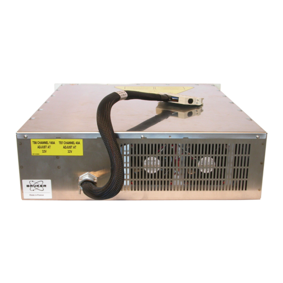
Safety Manufacturer’s Name Plate 2.1.2 The BLAH1000 E Amplifier 700-900MHz can be identified by a manufacturer’s name plate at the back panel of the unit that contains the country of origin of manufacture. Made in France Figure 2.2. Manufacturer’s Name Plate... -
Page 9: Installation
The installation of the device must be done only by an authorized and qualified technician, in total accordance with the running standards. BRUKER BIOSPIN assumes no liability for the customer’s failure to comply with these requirements and is therefore not responsible or liable for any injury or damage that occurs as a consequence of non-approved installation. -
Page 10: Environment Requirements
The unit can be placed onto a secure flat surface. Power Requirements The BLAH1000 E Amplifier 700-900MHz is designed to be powered by an additional external switched power supply (P/N:W1304007). The connection to this power supply is realized via a 500mm cable fitted with a 15 pins DIN 41612-ERNI female connector and coming out from the rear panel of the amplifier. -
Page 11: Initial Turn On Procedure
Initial Turn on Procedure Initial Turn on Procedure The following list describes how to turn on the BLAH1000 E Amplifier 700- 900MHz and what should be seen as this occurs. Before starting this procedure, make sure that you have properly followed the instructions in section "System Check"... - Page 12 Installation 12 (53) BRUKER BIOSPIN Operating & Service Manual Version 002...
-
Page 13: Operation
Operation Front Panel Description The BLAH1000 E Amplifier 700-900MHz front panel is provided with 13 indicators for status monitoring, 7 RF connectors, 1 interface connector. Indicators 4.1.1 Normal operation is indicated when following LED's are ON. Table 4.1. Indicators Assignment +32V Indicates that all +32V supplies are applied. -
Page 14: Coaxial Connectors
Coaxial Connectors Assignment IN1, IN2, IN3 RF inputs of the embedded router, SMA type connector (female). Default entry is IN1 and allows to the BLAH1000 E to deliver full power at nominal +4dBm drive. MAIN OUT RF output of 1000W if MAIN OUT LED is on, N type connector (female). -
Page 15: Device Front View
ETH. 10/100 IN 3 AUX OUT MAIN OUT H1000/H100 BLNK 1000W/100W 1000W/100W Figure 4.1. BLAH1000 E Amplifier 700-900MHz Front Panel Design Figure 4.2. BLAH1000 E Amplifier 700-900MHz Front Panel View Operating & Service Manual Version 002 BRUKER BIOSPIN 15 (53) -
Page 16: Rear Panel Description
Operation Rear Panel Description The rear panel of the BLAH1000 E Amplifier 700-900MHz has a 500mm cable fitted with a 15 pin DIN 41612-ERNI female connector, coming out of the rear panel of the amplifier. Power Supply Connector 4.2.1 Table 4.4. -
Page 17: Device Rear View
Rear Panel Description Device Rear View 4.2.2 Figure 4.4. BLAH1000 E Amplifier 700-900MHz Rear Panel Design Figure 4.5. BLAH1000 E Amplifier 700-900MHz Rear Panel View Operating & Service Manual Version 002 BRUKER BIOSPIN 17 (53) -
Page 18: External Power Supply
Operation External Power Supply The external power supply has the Bruker Part Number P/N:W1304007. This part number has been established for identification of use by internal jumper settings. It provides a first output voltage channel of +32Vdc, 50A maximum with a current... -
Page 19: Rear Panel Description
The rear panel of the external power supply is provided with a 15 pin DIN 41612- ERNI male connector. Device Rear View 4.3.4 Figure 4.8. Power Supply Rear Panel Design Figure 4.9. Power Supply Rear Panel View Operating & Service Manual Version 002 BRUKER BIOSPIN 19 (53) - Page 20 Operation 20 (53) BRUKER BIOSPIN Operating & Service Manual Version 002...
-
Page 21: Technical Description
Technical Description System Overview The BLAH1000 E Amplifier 700-900MHz requires the additional Bruker Biospin Power Supply to provide : • A RF Output of 1000W and more on the Solid output MAIN OUT, over the full frequency range 650-900MHz when it is selected for Solid application with SEL H1000/H100 command controlled at TTL level low. -
Page 22: Figure 5.1. Blah1000 E Amplifier 700-900Mhz System Block Diagram
Reflected Forward SEL H1000/H100 Fan Status Heatsink Temperature Gating -15V +15V +3,3V Gating & SEL H1000/H100 Detection Routing Selection & BIS Figure 5.1. BLAH1000 E Amplifier 700-900MHz System Block Diagram 22 (53) BRUKER BIOSPIN Operating & Service Manual Version 002... -
Page 23: Figure 5.2. Embedded Router Block Diagram
System Overview +15V Routing Selection Figure 5.2. Embedded Router Block Diagram Operating & Service Manual Version 002 BRUKER BIOSPIN 23 (53) -
Page 24: Figure 5.3. Driver & Relay Switch Block Diagram
Technical Description SEL H1000/H100 Gating H100 Bias H1000 Gating SEL H1000/H100 Gating Detection Figure 5.3. Driver & Relay Switch Block Diagram 24 (53) BRUKER BIOSPIN Operating & Service Manual Version 002... -
Page 25: Theory Of Operation
Theory of Operation RF Path 5.2.1 The BLAH1000 E Amplifier 700-900MHz (P/N: W1345091) consists of a 3 input embedded router, a class A / AB driver amplifier, a class AB power amplifier, a bi-directional high dynamic coupler and a mechanical RF Relay. -
Page 26: Rf Relays H1000/H100 Selection
The RF Combiner acts as a 2 ways in-phase combiner between the outputs of the power amplifier and the mechanical relay and feeds the power to the input of the bi-directional high dynamic coupler. 26 (53) BRUKER BIOSPIN Operating & Service Manual Version 002... -
Page 27: Rf Coupler
The peak power limitation is checked for each sample (10 million samples per second), and the maximum peak value is latched then cleared by a read operation (for monitoring purpose). Operating & Service Manual Version 002 BRUKER BIOSPIN 27 (53) -
Page 28: Figure 5.5. Forward Pulse Width Limitation
Other protections The control board also detects the following faults : - Power supply fault - Fan failure - Heat sink temperature to protect against thermal overstress - Fault detection timings 28 (53) BRUKER BIOSPIN Operating & Service Manual Version 002... -
Page 29: Bla Extension Board
"Indicators" on page 13 and "BLA Control Board" on page 27. BIS Board 5.2.5 The universal BIS board is located on the amplifier case and contains identifications of the amplifier. Operating & Service Manual Version 002 BRUKER BIOSPIN 29 (53) -
Page 30: Supply Status Board
In this case, the gating signal is disabled while the default is visualized on the front panel LED’s display. Technical help : please contact your local representative. 30 (53) BRUKER BIOSPIN Operating & Service Manual Version 002... -
Page 31: Servicing The Bla
Check the front panel of the amplifier, LED's indicators +32V, +15V, -15V and +3.3V ON must have lit. To access the BLAH1000 E Amplifier 700-900MHz, type "ha" in TOPSPIN 2.5x or better and choose the BLA that should be accessed or start your favourite web browser and type the given IP address as URL. -
Page 32: Sub Toolbar Information
In the main toolbar, we can see that a BLA is displayed. The left panel is the navigation menu. It can be used to navigate through the service pages or choose another tab in the sub toolbar. 32 (53) BRUKER BIOSPIN Operating & Service Manual Version 002... -
Page 33: Amplifier Status
Sub Toolbar Information Amplifier Status 6.2.2 Leads you to a page giving information about the current status of the amplifier. Figure 6.2. Amplifier Status (High Resolution) Figure 6.3. Amplifier Status (Solid) Operating & Service Manual Version 002 BRUKER BIOSPIN 33 (53) -
Page 34: Sub Toolbar Advanced Operations
This page gives you general information about the amplifier. The left panel is the navigation menu. It can be used to navigate through the service pages or choose another tab in the sub toolbar. 34 (53) BRUKER BIOSPIN Operating & Service Manual Version 002... -
Page 35: Amplifier Limitations
Leads you to a page giving several default and current limits of the amplifier. If you want, for any reasons, to change the current limits of the amplifier, press Change limits. Figure 6.5. Amplifier Limitations (High Resolution) Figure 6.6. Amplifier Limitations (Solid) Operating & Service Manual Version 002 BRUKER BIOSPIN 35 (53) -
Page 36: Change Limits
Servicing the BLA Change Limits 6.3.3 Read the warnings, change limit parameters and press Apply if you are sure of that. Figure 6.7. Change Limits (High Resolution) Figure 6.8. Change Limits (Solid) 36 (53) BRUKER BIOSPIN Operating & Service Manual Version 002... -
Page 37: Routing Information And Setting
Read the warnings, it is allowed to change routing configuration of the input router (ex: new route INPUT 2 to CHANNEL 1), press set new route if you are sure of that. Operating & Service Manual Version 002 BRUKER BIOSPIN 37 (53) -
Page 38: Sub Toolbar Maintenance
This page gives you general information about the amplifier. The left panel is the navigation menu. It can be used to navigate through the service pages or choose another tab in the sub toolbar. 38 (53) BRUKER BIOSPIN Operating & Service Manual Version 002... -
Page 39: Self-Test & Software Reset
Both operations can be done if the amplifier doesn't work correctly. Figure 6.11. Perform Self Test and Report Read the warnings, press Start the Self Test. You should have only gray lines in the report. Operating & Service Manual Version 002 BRUKER BIOSPIN 39 (53) -
Page 40: Figure 6.12.Perform Software Reset And Report
Servicing the BLA Figure 6.12. Perform Software Reset and Report Read the warnings, press Perform Software Reset. You should have the following screen. 40 (53) BRUKER BIOSPIN Operating & Service Manual Version 002... -
Page 41: Firmware Update
Read the warnings, press the Browse button for selecting the new firmware file to download and press Update. Download the new firmware will take a few minutes. NOTE : This button caption depends on your operating system language settings. Operating & Service Manual Version 002 BRUKER BIOSPIN 41 (53) -
Page 42: Bis Content
Servicing the BLA BIS Content 6.4.4 Leads you to a page giving information about the current BIS programmed on the amplifier. Figure 6.14. BIS Content 42 (53) BRUKER BIOSPIN Operating & Service Manual Version 002... -
Page 43: Specifications
Power Requirements Additional 208-230 VAC ± 10% single phase 50-60Hz switched power supply, Bruker Biospin part number W1304007. A front panel circuit breaker turns the AC Line ON/OFF. A status led board, on the front panel, indicates the power supplies condition. -
Page 44: General Specifications
Duty Cycle (Internal Limitation) 25% @ 100W (up to 100% @ 25W) Droop & Pulse Flatness ±2% typical @ 100W for 100ms Pulse Width Amplitude Stability vs. Temperature ±0.1% / °C max. 44 (53) BRUKER BIOSPIN Operating & Service Manual Version 002... -
Page 45: Channel Solid 1000W Output
Duty Cycle (Internal Limitation) 5% @ 1000W (up to 100% @ 50W) Droop & Pulse Flatness ±3% typical @ 1000W for 100ms Pulse Width Amplitude Stability vs. Temperature ±0.15% / °C max. Operating & Service Manual Version 002 BRUKER BIOSPIN 45 (53) - Page 46 Specifications 46 (53) BRUKER BIOSPIN Operating & Service Manual Version 002...
-
Page 47: Service Information And Maintenance
Every intervention on the device must be carried out by an authorized and qualified person. Any failure due to a non-respect of the following instructions will not be attributable to BRUKER BIOSPIN and will not be covered by the guarantee clauses. - Page 48 9. Put the coverage plate on the amplifier and screw it. 10. Put the amplifier in the NMR console, connect all cables on the front panel and the supply connector on the rear panel of the external power supply. 48 (53) BRUKER BIOSPIN Operating & Service Manual Version 002...
-
Page 49: Figures
Figure 2.2. Manufacturer’s Name Plate ..............8 3 Installation 4 Operation Figure 4.1. BLAH1000 E Amplifier 700-900MHz Front Panel Design ...... 15 Figure 4.2. BLAH1000 E Amplifier 700-900MHz Front Panel View ......15 Figure 4.3. DIN 41612-ERNI Connector Design ............. 16 Figure 4.4. - Page 50 Figures 7 Specifications 8 Service Information and Maintenance Figure 8.1. Push Fan Assembly ................48 50 (53) BRUKER BIOSPIN Operating & Service Manual Version 002...
-
Page 51: Tables
Table 7.1. Amplifier Common Characteristics ............43 Table 7.2. Channel High Resolution 100W Output Specifications ......44 Table 7.3. Channel Solid 1000W Output Specifications ........45 8 Service Information and Maintenance Operating & Service Manual Version 002 BRUKER BIOSPIN 51 (53) - Page 52 Tables 52 (53) BRUKER BIOSPIN Operating & Service Manual Version 002...
- Page 53 End of Document Operating & Service Manual Version 002 BRUKER BIOSPIN 53 (53)
- Page 54 Bruker BioSpin, your solution partner Bruker BioSpin provides a world class, market leading range of analysis solutions for your life and materials science needs. Bruker BioSpin Group info@bruker biospin.com www.bruker biospin.com...
Need help?
Do you have a question about the BLAH1000 E and is the answer not in the manual?
Questions and answers