Table of Contents
Advertisement
Quick Links
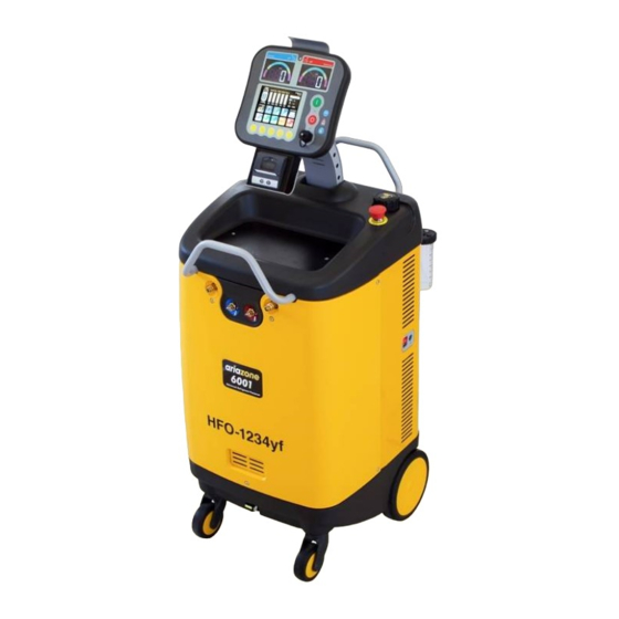
Ariazone 6001
HFO-1234yf
(with internal identifier)
Automotive Air-Conditioning Service Station
OPERATOR MANUAL
This equipment has been
extensively researched, designed
and developed with the prime
objective in satisfying the workshop
operator and technician in carrying
out the most efficient air-
conditioning diagnostic and service
procedure.
Please follow the proceeding
instructions carefully. If there is
anything you do not understand fully
in the proceeding text or images,
please do not hesitate to contact
your local distributor or
manufacturer.
IMPORTANT: This manual contains
important information pertinent to
operator safety, and must
accompany the unit, in the case of
sale or transfer to another party.
-----------------------------------------------------
Manufacturer reserves the right to modify
this manual and the unit itself at any time
without prior notice
1
Advertisement
Table of Contents

Summary of Contents for ariazone 6001
- Page 1 Ariazone 6001 HFO-1234yf (with internal identifier) Automotive Air-Conditioning Service Station OPERATOR MANUAL This equipment has been extensively researched, designed and developed with the prime objective in satisfying the workshop operator and technician in carrying out the most efficient air- conditioning diagnostic and service procedure.
-
Page 2: Table Of Contents
Contents Page 1. Introduction......................... 3 2. SAFETY FIRST! Important Safety Information's ............4 3. Technical Specifications....................5 4. Preparing the Machine for the First Use ..............6 5. Main Components & Features ..................7 6. Switching ON the Machine ..................9 7. -
Page 3: Introduction
1. Introduction Ariazone 6001 – HFO1234yf is a user-friendly tool specifically designed for the automotive air- conditioning technicians to carry out the following functions: Testing air-conditioning system Refrigerant identification. Recover and recycling the refrigerant from air-conditioning system. Electronically gauge amount of refrigerant recovered from air-conditioning system. - Page 4 2. Important Safety Information's_ This unit is simple and reliable in selecting and performing all its functions. Therefore, the user is not exposed to any risk, if the general safety guidelines reported below are followed, in association with proper use and maintenance of the unit (improper use and maintenance will reduce the safety of the unit).
-
Page 5: Technical Specifications
3. Technical Specifications Refrigerant HFO-1234yf Refrigerant Identifier R1234yf, R134, HC, Air (non-condensables), R22 Electronic scale +/- 5g resolution Load cell 60kg with 150% overload capacity Display 5.7” Touch screen LP and HP gauges High Clarity Digital Display Recovery cylinder 12kg Recovery pump Danfoss SC12G, Recovery rate... - Page 6 4. Preparing the Machine for Use Perform the following steps to prepare the unit before the first use. 1. Remove the carton box and styrofoam inserts. 2. Check to ensure that all of the accessory components are with the unit: - Power lead - Service hoses with quick couplers - User's manual...
-
Page 7: Main Components & Features
5. Main Components & Features Note: No hand valves are incorporated on the unit. A series of electronically controlled valves are incorporated to precisely control the functionality of the machine. 1. LP (Suction) and HP (Discharge) Digital Display - A large 80 mm x 50 mm digital displays shows A/C suction pressures (low and high pressure). - Page 8 8. New Oil 2 Injection vessel - A large capacity vessel of 300ml is mounted on the right side of the unit to electronically inject the oil in to the A/C system. 9. New Oil 3 /UV dye Injection vessel (OPTIONAL) - A large capacity vessel of 250ml is mounted on left rear side of the unit to electronically inject the oil (or UV dye) in to the A/C system.
-
Page 9: Switching On The Machine
6. Switching ON the Machine Switch ON the machine power switch. After the welcome menu, the machine will display the number of hours left before the maintenance service is required. Followed by self purge and hose evacuation (if necessary). This special function will prevent non- condensable (air) to be pushed in to the cylinder, therefore maintaining maximum refrigerant purity. -
Page 10: Icons And Their Meaning
7.1. Key icons and their meaning Cancel symbol Enter Confirm Return, returning to previous menu Left arrow, back Right arrow, scrolling right Down arrow, scrolling down Up arrow, scrolling up Minus (Decrease) Plus (Increase) Delete all Edit Symbols Print the report Unit set up Basic settings Advanced settings... - Page 11 Refrigerant transfer Set refrigerant weight function Full transfer (transferring the Change service hose selection entire amount of refrigerant from the cylinder) Recovery function Full recovery (removing the entire refrigerant from the air- con system) Open flow only on discharge - Open flow on both service High Pressure service hose hoses Low and High Pressure...
-
Page 12: Warning Icons
7.2. Warning icons and their meaning Refrigerant in the a/c No refrigerant in the a/c system, machine will system, machine will not not start evacuate start Recovery process. process. Automatically will start Recovery. Refrigerant cylinder on Refrigerant cylinder on machine is empty. machine is full. -
Page 13: Printer Set Up
8. Printer Set Up The printer is equipped with two keys and green led: >> Paper feed II on line / off line The green led shows the state of the printer: - Led constantly ON - Printer in line - Led blinking - Printer not in line or no paper - Led off - Press II. -
Page 14: Storage Cylinder Filling Procedure (Refrigerant Transfer)
9. Storage Cylinder Filling Procedure (Refrigerant Transfer) The purpose of the Refrigerant Transfer mode is to transfer new refrigerant from a storage cylinder into the machine cylinder. Note: The machine refrigerant cylinder which is situated behind the cylinder cover is supplied empty of refrigerant. - Page 15 There are 2 options when transfering refrigerant: 1. To select weight to be transfered, touch the Weight icon ... amount of refrigerant (in gr) to be transferred and by using the keypad select desired… into the machine cylinder and touch Confirm icon. 2.
- Page 16 Before transfer process start, the machine will self purge (if required). During the transfer process the machine will display the amount of refrigerant being recovered. This process can be paused by pressing Stop button and abort the function totally by pressing the Stop button again or restart the process by pressing the Start button.
-
Page 17: Connecting And Testing The A/C System
10. Connecting and testing the A/C system Use the service hose quick couplers to connect the hoses to the A/C system service ports, bearing in mind that BLUE must be connected to the low-pressure (suction) side and RED to high pressure (discharge) side. Important: Before connecting the quick couplers, clean the a/c ports of any foreign material (grease or dust). -
Page 18: Recovery & Recycling Mode
11. Recovery & Recycling Mode The purpose of the Recovery & Recycling mode is to recover refrigerant from the air conditioning system, which will condense, purify and store the liquid refrigerant in the unit cylinder ready for re-use. To select Recovery function, touch the Recovery icon. The display shows last used selection (usually operator just confirms 100% selection). - Page 19 … press the start button to start the recovery process NOTE: Machine will NOT START if there is no pressure in the hoses. While analyzing, display will show: If results are good will be printed and the machine will If results are not good machine will abort continue with Recovery process.
- Page 20 Once the machine has reached a vacuum of -25 kPa it will enter into recovery pause for duration of 2 minutes to allow for any remaining refrigerant in the A/C system (if any) to boil off. If the pressure in the A/C system increases above 0 kPa the machine will automatically return in to recovery re- run to the remove the rest of the refrigerant which has boiled off in the A/C system.
-
Page 21: Evacuation Mode
12. Evacuation Mode In the evacuation mode the air and moisture in the air conditioning system is removed and exhausted to the atmosphere. The evacuation mode runs for a predetermined time selected by the operator. To select the Evacuation mode, touch the The display shows last used selection. - Page 22 When the above selections have been made, touch and Press Start button to start the evacuation Confirm icon. function. The evacuation function start running for the duration of the time which has been selected. If the evacuation function is selected and there is residual refrigerant in the air conditioning system, the unit would detect this condition and warn the operator.
-
Page 23: Oil & Uv Dye Injection Mode
13. Oil & UV Dye Injection Mode The purpose of this function is to batch a user-defined quantity of refrigerant oil or UV dye Important: A/C system must be properly evacuated, before new oil or UV dye is injected into. To select the Oil injection function, touch the Oil The display shows last used selection. - Page 24 By using the keypad select oil volume (ml) and touch When the desired selection has been made, touch Enter icon to confirm. Confirm icon. Press Start button to start the oil injection function. Oil injection in progress display. Once the selected function has been completed successfully this screen will be displayed.
-
Page 25: Refrigerant Charge Mode
14. Refrigerant Charge Mode The purpose of the refrigerant charge mode is to batch a user-defined weight amount of refrigerant into the air-conditioning system. Important: A/C system is always must be properly evacuated and leak tested, before refrigerant is charged To select Charge function, touch the refrigerant The display shows last used selection. - Page 26 Select the vehicle model and touch Enter icon. Select the vehicle engine and touch Enter icon. Select the vehicle production year and touch Enter When the desired selection has been made, touch icon. Confirm icon. Touch Enter icon to confirm selection. Press Start button to start the charge function.
-
Page 27: Auto Mode Function
15. Auto Mode Function The unit incorporates a Fully Auto function, where the operator simply sets the parameters and the machine will perform and complete all operations automatically without any further intervention from the operator. Each operation is recorded and printed at the completion of the full cycle. If any fault is detected during the fully auto cycle the unit will warn the operator. - Page 28 To change charge amount, touch the refrigerant To set the refrigerant weight touch the Weight icon, Charging icon. or refrigerant charge weight can be selected by using database by touching the Car icon. See Charge Function (page 24). Select the desired A/C service port (or both). When the desired selection has been made, touch Full automatic function should be done with both Confirm icon.
-
Page 29: Cylinder Air Purge
16. Cylinder Air Purge_ Once a week before using machine, check if there is non-condensable (air) build up in the refrigerant cylinder. First, measure the ambient temperature. Then read the cylinder pressure on front display and compare it with the temperature pressure chart, affixed to the machine. If the cylinder pressure is higher than the pressure/temperature chart, there are non-condensable gases (air) in the unit cylinder. -
Page 30: A/C Flushing Mode
17. A/C Flushing Mode (OPTIONAL) The purpose of the A/C flushing mode is to clean the A/C system inside from dirt and particles. A/C system is cleaned by flushing it with liquid refrigerant with high flow rate and against the normal flow direction. Important: The flushing procedure should only be preformed when the compressor has been disconnected from the A/C system including orifice tube or expansion valve. - Page 31 Touch Compressor icon. and select both a/c ports (middle icon) Touch Leak Test icon. Select min.3 minutes leak test under vacuum and touch Enter icon to confirm When the above selections have been made, and Press Start button to start the evacuation touch Confirm icon.
- Page 32 To select the flushing mode touch the flush icon To activate Flushing function contact your distributor. When function activated and external filtration kit is By using the keypad, select flushing time and touch fitted, touch the time icon to select the flushing time Enter icon to confirm.
-
Page 33: Settings & Optional Functions
18. Settings & Optional Functions 18.1. Main Unit Set Up To enter into the Set Up Mode, touch the main Touch the unit Set Up icon (left bottom). Settings icon. The display will show the unit Set Up main screen. With Up and Down keys select the desired function followed by touching the Edit button to make the desired changes. -
Page 34: How To Set The Workshop Data On Print Report
18.2. How to set the workshop data on print report? Enter into the Set Up Mode by touching the main Touch the unit Set Up icon (left bottom). Settings icon. With arrows keys UP and DOWN select WORKSHOP With (+) and/or (–) keys set the workshop to be ON. and press Edit icon. -
Page 35: Wireless Temperature Sensor Set Up
18.3. Wireless Temperature Sensors Set Up (Optional) Enter into the Set Up Mode. Touch the Wireless Sensor icon. Press and hold the wireless temp sensor button until The sensor is still not set. Touch Sensor type icon to the sensor data appears on the display. select appropriate sensor. -
Page 36: Refrigerant Management, Operation History And Working Hours Reset
18.4. Refrigerant Management, Operation History and Working Hours Reset Touch the main Set Up icon. Touch the Sum icon. The display will show the cycle operation history. The operator can read total recovered refrigerant and/or oil weight, total charge weight and total refrigerant transfer. -
Page 37: Refrigerant Recycling
18.5. Refrigerant Recycling The purpose of the Refrigerant Recycling mode is to purify the refrigerant from other recovery cylinder which has not been attached to this machine. Remove the cylinder cover. Turn off the cylinder valves and cylinder hose ball valves (red and blue). Carefully disconnect the hoses from cylinder (wear protective glasses and gloves). - Page 38 EC D E C L A R A T I O N OF C O N F O R M I T Y The company: Ariazone International - Europe Hereby declares that the product: Ariаzone 6001 HFO 1234yf - Automotive A/C Service Station Meets all requirements of European Directives: 2006/95/EC (ex 73/23/EEC) Low Voltage Directive...
Need help?
Do you have a question about the 6001 and is the answer not in the manual?
Questions and answers