Table of Contents
Advertisement
Quick Links
Advertisement
Table of Contents

Subscribe to Our Youtube Channel
Related Manuals for TERASAKI TemTripPRO

Summary of Contents for TERASAKI TemTripPRO
- Page 1 TemTripPRO MOTOR PROTECTIVE RELAY (Type PRS-1S) INSTRUCTION MANUAL Be sure to read this instruction manual before using the product. Keep this manual handy and safely. Make sure that the product is set, adjusted or tested by a competent person.
-
Page 2: Table Of Contents
Table of Contents 1. Safety Notices ................................. 3 2. Specifications .................................. 4 3. Characteristics ................................5 4. Component Identifications ............................10 5. Installation ..................................11 6. Connection ..................................12 6-1. Circuits and Ratings ............................12 6-2. Terminal Connection Procedure ........................13 7. -
Page 3: Safety Notices
1. Safety Notices Thank you for purchasing the TERASAKI motor protective relay, TemTrip PRO. This chapter contains important safety information. Be sure to carefully read these safety notices, instructions in this manual, and other documents accompanying the motor protective relay (herein referred to as the "protective relay") to familiarize yourself with safe and correct procedures or practices before using the protective relay. -
Page 4: Specifications
2. Specifications Specifications of the type PRS-1S protective relay are shown in Table 1 below. Table 1 Specifications of protective relay (●: Standard feature, ○: Option) Presence/abse Reference section ● 3, 7-4-3 Applied current anomaly detection setting*2 ● 3, 7-4-3-1 Overload element detection *1 *2 ●... -
Page 5: Characteristics
3. Characteristics 3-1. Representation Format of Type Type: PRS-1S N T 1 ① ② ③ Specification Symbol Description Without communication function ① Communication function With communication function THERMISTOR ② Temperature sensor type ③ CT rated current 3-2. About Characteristic Settings Table 2 shows the characteristic settings of the protective relay. - Page 6 Table 2 Characteristic settings parameter (continued) Protective function Selection Setting range STEP Remarks (1 –250)s Motor startup time TRIP / ALARM / 1s ±2%+0.1-0s (When the calculated value detection setting is time equal to or greater than 1.10 x overload pick (1 –10) "Too Many...
- Page 7 Table 2 Characteristic settings parameter (continued) Protective Selection Setting range STEP Remarks function (4.00 –12.00) X In Short-circuit TRIP / OFF 0.10 ±10% This function is for short-circuit protection. It can be activated when protection the motor is started or running. (0.0 –4.0)s 0.1s ±10%±25ms Short-circuit protection becomes...
- Page 8 Table 2 Characteristic settings parameter (continued) Protective Selection Setting range STEP Remarks function Unbalanced TRIP / ALARM / OFF "Unbalanced current current protection protection setting (LVL1)" is setting (LVL1) 50% ±2% (relative to the set value) of "Unbalanced current protection setting (LVL2)". Time limit: 5 s (Not adjustable) (0.20 –0.40) ×...
- Page 9 3-3. Characteristic Curve Figure 1 shows the operating characteristic curve of the protective relay. Motor heating trip Overload trip Short-time delay trip Trip caused by unbalanced current Figure 1 Operating characteristic curve of the protective relay KRB-5426c...
-
Page 10: Component Identifications
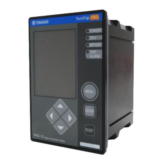
4. Component Identifications Figure 1 provides general views of the protective relay. ③ POWER lamp Lit in white while control power is being applied ① Display screen ③ ④ CPU lamp ④ Lit in green while the internal CPU is ⑤... -
Page 11: Installation
5. Installation This chapter describes how to install the protective relay. 1) External dimensions and panel drilling plan See Figure 3 below. The thickness of each panel is 2 to 4 [mm]. Front view Side view Rear view Panel drilling plan Figure 3 External dimensions and panel drilling plan of the protective relay 2) Install and remove the mounting tool method (Install) -
Page 12: Connection
6. Connection 6-1. Circuits and Ratings The connection diagram and terminal description of type PRS-1S protective relay are shown in Figure 5 and Tables 3, respectively. External command 1 Wiring for 43, 46, and 49 is not required for thermistor External specification. -
Page 13: Terminal Connection Procedure
6-2. Terminal Connection Procedure CAUTION After connecting each wire to the connector, recheck their respective connection positions. Incorrect connections may result in failure. Figures 6-1 and 6-2 show the connection procedure. ① Press each connector release button (orange) with a small flathead screwdriver. ②... -
Page 14: How To Display Measurements And Make Settings
7. How to Display Measurements and Make Settings CAUTION Make sure that the protective relay is adjusted by a competent person. The following describes how to display measurements and make settings of the protective relay. 7-1. General 1) Make sure that control power is supplied. Control power supply is required to display measurements. 2) The MENU, arrow (up, down, right, left), ENTER, and RESET buttons (seven buttons in total) are used to display measured values and set characteristics. -
Page 15: Navigation To Each Setting Item Screen After Power On (From Ini-A-1 Through To Ma-A-1)
7-2. Navigation to Each Setting Item Screen After Power ON (from INI-A-1 through to MA-A-1) This motor protective relay is provided with measured value display items, characteristic value setting items, and maintenance items that are used to display histories and conduct function checks. Figure 8 below shows how to navigate to each item. Initial screen This screen (INI-A-1) is displayed after the power is turned on. -
Page 16: Navigating Between Measured Value Display Item Screens (From Mo-A-1 Through To Mo-G-2)
7-3. Navigating between Measured Value Display Item Screens (from MO-A-1 through to MO-G-2) Figure 9 shows how to navigate between measured value display item screens (from MO-A-1 through to MO-G-2). See Table 4 for items that are actually displayed on the screen. Figure 9 Navigating between measured value display item screens (from MO-A-1 through to MO-G-2) KRB-5426c -16-... - Page 17 Table 4 Display items and descriptions of measured value display item screens (MO-A-1to MO-G-2) Screen Display Item Remarks IMAX INST Maximum phase current value (present value) Phase 1 (R-phase, A-phase) current value (present I1 INST value) Phase 2 (S-phase, B-phase) current value (present I2 INST value) MO-A-1...
-
Page 18: Navigating Between Characteristic Value Setting Item Screens (From S-A-1 Through To S-D-1)
7-4. Navigating between Characteristic Value Setting Item Screens (from S-A-1 through to S-D-1) Figure 10 shows how to navigate between characteristic value setting item screens (from S-A-1 through to S-D-1). See Table 5 for items that are actually displayed on the screen. See the setup screens in 7-4-1. - Page 19 Table 5 Setting items and display details of characteristic value setting item screens (S-A-1 through to S-D-1) Screen No. Setting items and display details Remarks Display Item S-A-1 SET UP Initial display of setting mode LOAD INCREASE Applied current anomaly detection setting S-B-1 O/C LVL1-JAM Overload protection setting...
-
Page 20: Navigating Between Setup Item Screens (From S-A-1 Through To Su-L-1)
7-4-1. Navigating between setup item screens (from S-A-1 through to SU-L-1) Figures 11 to 11-2 show how to navigate between setup item screens (from S-A-1 through to SU-L-1). See Table 6 for items that are actually displayed on the screen. When each setting item is changed, your password needs authentication once. Refer to "7-4-2. Navigating between password setting/authentication screens". - Page 21 SU-D-1 You can set each item in the same way as (a) above. SU-L-1 Figure 11-1 Navigating between setup item screens (from SU-E-1 through to SU-M-1) KRB-5426c -21-...
- Page 22 SU-M-1 See the password setting screens in 7-4-2. Figure 11-2 Navigating between setup item screens (SU-L-1) Table 6 Setting items and display details of setup item screens (S-A-1 to SU-L-1) Screen Setting items and display details Selection Setting range Remarks number Display Item...
-
Page 23: Navigating Between Password Setting/Authentication Screens (From Su-L-1 Through To P-A-4)
7-4-2. Navigating between password setting/authentication screens (from SU-L-1 through to P-A-4) Figure 12 shows how to navigate between password setting screens (from SU-L-1 through to SU-L-6). See Table 7 for items that are actually displayed on the screen. [E]: Updates the password [L]: Does not update the password For SU-L-2, SU-L-3, SU-L-4, and SU-L-5, as in the case with SU-L-2 →... - Page 24 Figure 12-1 shows how to navigate between password authentication screens (from P-A-1 through to P-A-4). See Table 7-1 for items that are actually displayed on the screen. Your password needs authentication in the following cases: When you press the [M] button to navigate to the maintenance item screen or measured value display item screen as shown in 7-2 and then change settings for each setting item on the characteristic value setting item screen ...
-
Page 25: Navigating Between Setting Item Screens (From S-A-1 Through To St-A2-3①)
7-4-3. Navigating between setting item screens (from S-A-1 through to ST-A2-3①) Figure 13 shows how to navigate between setting item screens (from S-A-1 through to AT-A2-3① ). See Table 8 for items that are actually displayed on the screen. S-B-2① See the setting screens 7-4-3-3. - Page 26 Table 8 Setting items and display details of setting item screens (S-A-1 to AT-A2-3①) (overcurrent anomaly detection setting) Screen Setting items and display details Selection Setting range Remarks number Display Item S-B-1 Initial display of setting mode Refer to page 18. Use the [U] or [D] arrow button to switch the item to S-B-2 Setting item selection switching...
-
Page 27: Navigating Between Setting Item Screens (From S-B-2① Through To St-B2-1)
7-4-3-1. Navigating between setting item screens (from S-B-2① through to ST-B2-1) Figure 14 shows how to navigate between setting item screens (from S-B-2① to ST-B2-1). See Table 9 for items that are actually displayed on the screen. You can set each item in the same way as (a). - Page 28 Table 9 Setting items and display details of setting item screens (S-B-2① to ST-B2-1) (overload protection setting) Setting items and display details Screen number Selection Setting range Remarks Display Item This screen is displayed when you press the Setting item switching [D] arrow button once at the S-B-2 screen S-B-2①...
-
Page 29: Navigating Between Setting Item Screens (From S-B-2② Through To St-C2-1)
7-4-3-2. Navigating between setting item screens (from S-B-2② through to ST-C2-1) See Table 10 for items that are actually Figure 15 shows how to navigate between setting item screens (from S-B-2② through to ST-C2-1). displayed on the screen. You can set each item in the same way as (a). - Page 30 Table 10 Setting items and display details of setting item screens (S-B-2② to ST-C2-1) (short-circuit protection setting) Setting items and display details Screen number Selection Setting range Remarks Display Item This screen is displayed when you press the S-B-2② Setting item switching [D] arrow button twice at the S-B-2 screen (shown on page 25).
-
Page 31: Navigating Between Setting Item Screens (From S-C-1 Through To St-L-1)
7-4-3-3. Navigating between setting item screens (from S-C-1 through to ST-L-1) Figures 16 shows how to navigate between setup item screens (from S-C-1 through to ST-F2-1). See Table 11 for items that are actually displayed on the screen. You can set each item in the same way as (a). - Page 32 Table 11 Setting items and display details of setting item screens (S-C-1 to ST-F2-1) (OVERLOAD PICKUP setting) Setting items and display details Screen number Selection Setting range Remarks Display Item S-C-1 Initial display of setting mode See page 18. Use the [U] or [D] arrow button to S-C-2 Setting item selection switching switch the item to be set.
- Page 33 Figure 16-1 shows how to navigate between setting item screens (from S-C-2① through to ST-H2-1). See Table 11-1 for items that are actually displayed on the screen. S-C-2① You can set each item in the same way as (a). ② S-C-2 Figure 16-1 Navigating between setting item screens (from S-C-2①...
- Page 34 Table 11-1 Setting items and display details of setting item screens (S-C-2① to ST-H2-1) (unbalanced current protection setting) External output Setting items and display details Setting setting screen Selection Remarks range Display Item number This screen is displayed when you press the [D] arrow S-C-2①...
- Page 35 Figure 16-2 shows how to navigate between setting item screens (from S-C-2② through to ST-J2-1). See Tables 11-2 and 11-3 for items that are actually displayed on the screen. ① S-C-2 You can set each item in the same way as (a). ④...
- Page 36 Table 11-2 Setting items and display details of setting item screens (S-C-2① to ST-I2-1) (motor startup time monitor setting) External output Setting items and display Setting details setting screen Selection Remarks range number Display Item This screen is displayed when you press the [D] arrow button Setting item selection S-C-2②...
- Page 37 Figure 16-4 shows how to navigate between setting item screens (from S-C-2④ through to ST-L-1). See Table 11-4 for items that are actually displayed on the screen. ③ S-C-2 You can set each item in the same way as (a). Figure 16-4 Navigating between setting item screens (from S-C-2④...
- Page 38 Table 11-4 Setting items and display details of setting item screens (S-C-2④ to ST-L-1) (ground fault protection setting) External output Setting items and display details setting screen Selection Setting range Remarks Display Item number This screen is displayed when you press the [D] Setting item selection switching S-C-2④...
-
Page 39: Navigating Between Setting Item Screens (From S-D-1 Through To St-W-1)
7-4-3-4. Navigating between setting item screens (from S-D-1 through to ST-W-1) Figure 17 shows how to navigate between setting item screens (from S-D-1 through to ST-N2-1). See Table 12 for items that are actually displayed on the screen. Screen transition differs according to the TEMP SENSOR... - Page 40 Table 12 Setting items and display details of setting item screens (S-D-1 to ST-N2-1) (temperature detection setting) Screen Setting items and display details Selection Setting range Remarks number Display Item S-D-1 Initial display of setting mode See page 25. This screen is displayed when you press the [D] arrow button ST-D-2 Setting item selection switching once at the S-D-1 screen (shown on page 25).
- Page 41 Figure 17-1 shows how to navigate between setting item screens (from S-D-2① through to ST-S-1). See Tables 12-1 and 12-2 for items that are actually displayed on the screen. S-D-2 You can set each item in the same way as (a). ③...
- Page 42 Table 12-1 Setting items and display details of setting item screens (S-D-2① to ST-Q2-1) (open-phase protection setting) Screen Setting items and display details Selection Setting range Remarks number Display Item This screen is displayed when you press the [D] arrow button once at ST-D-2①...
- Page 43 Figure 17-2 shows how to navigate between setting item screens (from S-D-2④ through to ST-X2-1). See Table 12-3 for items that are actually displayed on the screen. S-D-2② ST-N2-1 You can set each item in the same way as (a). ④...
- Page 44 Table 12-3 Setting items and display details of setting item screens (ST-T-1 to ST-U-1) (undercurrent protection setting) Screen Setting items and display details Selection Setting range Remarks number Display Item The figure on the previous page shows the state in which Current protection setting item current value setting (H/C CURR) is selected.
- Page 45 Figure 17-3 shows how to navigate between setting item screens (from S-D-2④ through to ST-W-1). See Table 12-5 for items that are actually displayed on the screen. S-D-2③ You can set each item in the same way as (a). Figure 17-3 Navigating between setting item screens (from S-D-2④ through to ST-W-1) KRB-5426c -45-...
- Page 46 Table 12-5 Setting items and display details of setting item screens (S-D-2④ to ST-W-1) (external anomaly protection setting) Screen Setting items and display details Selection Setting range Remarks number Display Item This screen is displayed when you press the [D] arrow button once at the S-D-2③...
-
Page 47: Navigating Between Maintenance Item Screens (From Ma-A-1 Through To Ma-I-2)
7-5. Navigating between Maintenance Item Screens (from MA-A-1 through to MA-I-2) Figure 18 shows how to navigate between maintenance item screens (from MA-A-1 through to MA-E-1). See Tables 13 and 13-1 for items that are actually displayed on the screen. Test ends or [L] is pressed to cancel Blinking frame is 400ms cycle... - Page 48 Table 13 Setting items and display details of maintenance item screens (MA-A-1 to MA-C-2) Screen number Setting items and display details Selection Setting range Remarks See page 15. MA-A-1 Maintenance items The figure on the previous page shows the state in which the relay activation test item (RELAY TEST) is selected.
- Page 49 Figure 18-1 shows how to navigate between maintenance item screens (from MA-A-1② to MA-H-41). For items that are actually displayed on the screen, refer to Table 13-3 and "7-8. History and Trip/Alarm Activation Display Screens". MA-A-1② Figure 18-1 Navigating between maintenance item screens (from MA-A-1② through to MA-H-41) KRB-5426c -49-...
- Page 50 Table 13-3 Setting items and display details of maintenance item screens (MA-A-1② to MA-H-41) (history display) Screen No. Setting items and display details Remarks This screen is displayed when you press the [D] arrow button once at the MA-A-1 screen (shown on page 47). MA-A-1②...
- Page 51 Table 13-4 Setting items and display details of maintenance item screens (MA-A-1③ to MA-I-2) (communication status display (for specifications with communication facility)) Screen number Setting items and display details Remarks This screen is displayed when you press the [D] arrow button once at the MA-A-1③...
-
Page 52: Screen Transition In The Event Of Trip Or Alarm (Tr-A-1, Al-A-1)
7-6. Screen Transition in the Event of Trip or Alarm (TR-A-1, AL-A-1) Figures 19 and 19-1 show the respective screens in the event of trip and alarm activations. Pressing [M] returns the display to the pre-activation screen. For the display details of the trip or alarm activation screen, refer to "7-8. History and Trip/Alarm Activation Display Screens". -
Page 53: Function Test And Relay Test (From Ma-B-1 To Al-A-1)
7-7. Function Test and Relay Test (from MA-B-1 to MA-C-2) The protective relay allows the user to conduct two types of test: function test and relay test. (1) Function test (from MA-B-1 to AL-A-1) You can conduct function tests for overload protection (O/C L1-JAM) and short-circuit protection (O/C L2-SHORT). These tests are activation tests using values equivalent to 1.2 times the set values. - Page 54 (2) Relay test (from MA-C-1 to MA-C-2) You can conduct relay output tests for RY1 to RY4 as shown in Figure 20-1. When relay output occurs, an "R" mark appears on the bottom right of the screen. To perform a reset, press [R]. When pulse output is used, an automatic reset occurs. "RY1"...
-
Page 55: History And Trip/Alarm Activation Display Screens
7-8. History and Trip/Alarm Activation Display Screens Figure 21 shows the latest trip/alarm history screen, trip/alarm history list screen, and trip/alarm activation display screen, and Tables 15 and 15-1 explain the items displayed on these screens. Latest history screen History list screen Trip/alarm activation display screen Figure 21 Latest history screen, history list screen, and trip/alarm activation display screen Tables 14 Items displayed on the latest trip/alarm history screen, trip/alarm history list screen, and trip/alarm activation display screen... -
Page 56: Responses To Abnormal Events
Figure 21-1 shows the latest event history screen and event history list screen, and Tables 15-2 and 15-3 explain the items displayed on these screens. Latest event history screen Event history list screen Figure 21-1 Latest event history screen and event history list screen Table 15-2 Items displayed on the latest event history screen and event history list screen Display item ⑥... - Page 57 Circuit Breaker Division 6-13-47 Kamihigashi, Hiranoku, Osaka 547-0002, Japan Tel: 81-6-6791-2763 Fax: 81-6-6791-2732 Web Site: http://www.terasaki.co.jp E-mail: kiki-info@terasaki.co.jp Published in Mar. 2020 The contents of this manual may be subject to change without notice. Recycle paper used. KRB-5426c -57-...
Need help?
Do you have a question about the TemTripPRO and is the answer not in the manual?
Questions and answers