Sign In
Upload
Download
Table of Contents
Contents
Add to my manuals
Delete from my manuals
Share
URL of this page:
HTML Link:
Bookmark this page
Add
Manual will be automatically added to "My Manuals"
Print this page
×
Bookmark added
×
Added to my manuals
Manuals
Brands
HATO Manuals
Garage Door Opener
120
Automation manual
HATO 120 Automation Manual
Hide thumbs
1
2
Table Of Contents
3
4
5
6
7
8
9
10
11
12
13
14
15
16
17
18
19
20
21
22
23
24
page
of
24
Go
/
24
Contents
Table of Contents
Troubleshooting
Bookmarks
Table of Contents
Table of Contents
Purpose and Recommendations
Purpose
Recommendations
Characteristics
Device Description
Technical Specification
Maximum Working Ranges
External Dimensions
Elements Included in the Package
Installation
Assembly
Operation Buttons
External Connector
Checking the Corectness of Assembly
Programming and Adjustment
Programming the Opening and Closing Posistions
Adjusting the Sensitivity of the Overload Sensor
Installation of Photocells
Enable/Disable Auto Closing
Gate Lock Function
Programming the Remote Control
Final Steps
Environmental Protection
Mintenance
Troubleshooting
Recommendations for Users
Emergency Gate Opening and Closing
Advertisement
Quick Links
1
Table of Contents
2
Technical Specification
3
Installation
4
Operation Buttons
5
Programming and Adjustment
6
Programming the Remote Control
Download this manual
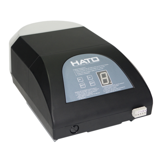
HATO 120/200
AUTOMATION MANUAL
FOR GARAGE DOORS
1
Table of
Contents
Previous
Page
Next
Page
1
2
3
4
5
Advertisement
Table of Contents
Need help?
Do you have a question about the 120 and is the answer not in the manual?
Ask a question
Questions and answers
Related Manuals for HATO 120
Garage Door Opener HATO 180C User Manual
Garage door operator (18 pages)
This manual is also suitable for:
200
Table of Contents
Print
Rename the bookmark
Delete bookmark?
Delete from my manuals?
Login
Sign In
OR
Sign in with Facebook
Sign in with Google
Upload manual
Upload from disk
Upload from URL


Need help?
Do you have a question about the 120 and is the answer not in the manual?
Questions and answers