Table of Contents
Advertisement
Advertisement
Table of Contents

Related Manuals for QYT KT-8900D


Summary of Contents for QYT KT-8900D
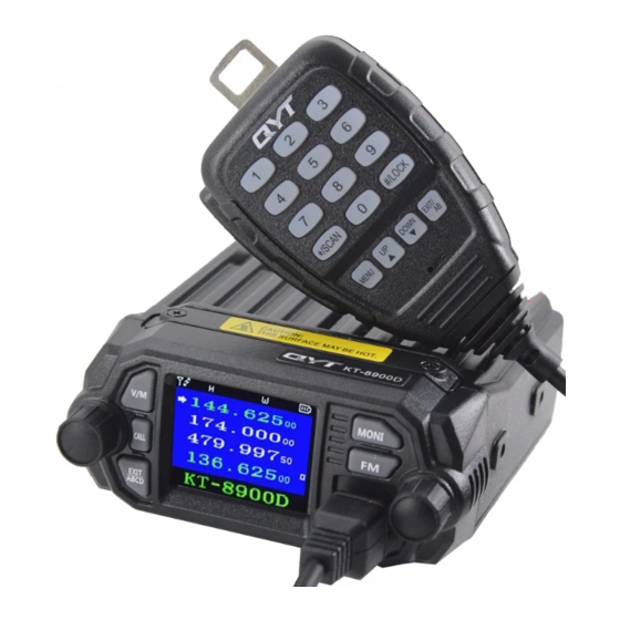
- Page 1 Mini color screen Mobile Radio USER'S MANUAL...
- Page 3 Thank you for your purchase of the product. This multi-band radio will deliver instant reliable communication. Please read this manual carefully before use! BEFORE PROCEEDING INSURE: • Qualified technicians shall service this equipment only. Do not modify the radio for any reason. •...
-
Page 4: Table Of Contents
TABLE OF CONTENTS GETTING STARTED ..........1 OTHER SETTINGS ..........29 Unpacking and Inspecting ........1 Toggle from High to Low Power ......29 Overview of the Front Panel ......... 2 Storing an FM Radio Station and Scanning ..29 Overview of the Rear Ports ........ -
Page 5: Getting Started
GETTING STARTED Unpacking and Inspecting • Please check the packaging of your radio for any signs of damage. • Carefully open the box, and confirm your received the items listed below. • If you find the radio or the included accessories are damaged or lost, immediately contact your dealer. What’s in the Box Mobile Radio Microphone... -
Page 6: Overview Of The Front Panel
Overview of the Front Panel Model 1 ® RJ45 Connector Data Input RPT CTRL +8V DC Out ® MIC Ground Null ® ® ® G) Power, On/Off Press + Volume Knob ]: when in standby, press to send caller ID (ANI) in the selected signaling mode;... - Page 7 Model 2 ® RJ45 Connector Data Input RPT CTRL +8V DC Out ® MIC Ground Null ® ® ® G) Power, On/Off Press + Volume Knob ]: when in standby, press to send caller ID (ANI) in the selected signaling mode; while transmitting, press to 0 V/M Mode Switch (Channel/Frequency) send activate signaling.
-
Page 8: Overview Of The Rear Ports
Overview of the Rear Ports ® G) TRRS Line Out: Includes PTT/Microphone/Audio-out/GND 0 DATA, Programming Jack ® Cooling Fan G) ® @ SO-239 RF Antenna Connector: Connects to PL-259 Antennas TRRS Line-Out Connector ® DC Power Input (13.8V–7A Peak) G) GND 0 SP ®... -
Page 9: Hand Held Mic Keys And Description
Hand Held MIC Keys and Description G) “MENU” : Function key ® VFO/MR Toggle (Long Press) ® 0 “UP” : Higher frequency ® ® “DOWN” : Lower frequency @ “EXIT” ® : Exit the AB channel switch, alarm function ®... - Page 10 G) “MENU” : Function key ® VFO/MR Toggle (Long Press) 0 “UP” : Higher frequency ® “DOWN” : Lower frequency ® @ “EXIT” : Exit the AB channel switch, alarm function ® Alarm Activate (Long Press) ® ® “*/SCAN” : Scanning function ®...
-
Page 11: Color Display And Icon Descriptions
Color Display and Icon Descriptions The Top Line on the LCD will show the current selected channel’s settings at a glimpse: Current Channel Setting Current Selected Channel Selection in Menu (applies to current selected channel) Icon Description Icon Description Icon Description Channel allowed to TX &... - Page 12 Main frequency indicator Strength Meter for the incoming signal Alternate ‘watched’ frequencies Numerical scale for the incoming transmission intensity indicator Dual, Tri or Quad Watch selected in “Menu 0: TMR”. Meter for the transmit output power - (High or Low Power inidcator) Numerical scale for microphone transmit Custom Boot audio level intensity...
-
Page 13: Antenna Basics
Antenna Basics Your Mobile Radio Kit does not include an Antenna. It is VERY Important to NOT transmit without a antenna or dummy load attached to the mobile radio. Doing so, will cause harm to the internal components of your radio. You will want to choose a suitable antenna for the bands you plan on transmitting and receiving on. - Page 14 Antenna Requirements Antenna SWR Rating : 1.5:1 or less (on the radio frequencies in use.) Antenna Impedance : 50 ohm (use 50 ohm rated coax and coax connectors). Antenna Grounding : Ensure the antenna is mounted with a grounding plane. R Visually Inspect Coax/Connectors for any Slits or Damage –...
-
Page 15: Basic Shortcuts And Use
BASIC SHORTCUTS AND USE Pound # Key (Keypad Lock) Turning the unit ON To enable or disable the keypad lock, press and To turn the unit on, simply push and hold the vol- hold the [#/LOCK] key for about two seconds. ume knob until it turns on. -
Page 16: Making A Call
Making a call Each press (or rotation click) will increment or dec- rement your frequency according to the frequency Press and hold the PTT button on the side of the step you've set your transceiver to (Menu Item 1: handheld mic to transmit. -
Page 17: Monitor Both Vfo & Mr Modes
Monitor Both VFO & MR Modes D Channel (MR) mode The use of Channel (MR) mode is dependent on You can toggle from VFO and MR (Memory Re- actually having programmed in some channels to call) mode by either pressing the [V/M] button on use. -
Page 18: Menu Quick Review
MENU QUICK REVIEW Quick Menu Settings 3. [Enter Menu]+[3]: TXP Sets the transmit power setting from HIGH to To set the Menu options from the Mobile body use LOW. the M Press the selector knob on the radio body (or 4. - Page 19 • ANI 9. [Enter Menu]+[9]: BEEP : Only automatically keyed DTMF codes are heard. Turns key beeps OFF or ON. • BOTH : All DTMF codes are heard. 10. [Enter Menu]+[1]+[0]: R-DCS 15. [Enter Menu]+[1]+[5]: BCL DCS receive/squelch settings. Options include Busy channel lock-out.
- Page 20 • EOT : send ID code at End of Transmit. 18. [Enter Menu]+[1]+[8]: OPTSIG • BOTH : send ID code at both beginning and Turn on the optional signaling. OFF the chan- nel or mode will not use optional signaling. end of transmit.
- Page 21 • NAME : displays assigned channel name. 24. [Enter Menu]+[2]+[4]: EMC-CH Alarm channel setting. This is the channel that 30. [Enter Menu]+[3]+[0]: CD-MDF the alarm will transmit the PTTID and Alarm Display Mode (Display D) sound on. • FREQ : displays Frequency. 25.
- Page 22 35. [Enter Menu]+[3]+[5]: MENUFC 40. [Enter Menu]+[4]+[0]: SIG-BC Menu LCD Display Foreground, Text Color: Signal Bar LCD Display Background Color: Color options are BLACK, WHITE, RED, Color options are BLACK, WHITE, RED, BLUE, GREEN, YELLOW, INDIGO, PURPLE, BLUE, GREEN, YELLOW, INDIGO, PURPLE, GRAY.
- Page 23 46. [Enter Menu]+[4]+[6]: SFT-D repeater. • OFF Frequency diff erence direction setting. : turned off . • OFF : no frequency diff erence. • CARRI : forwards after it receives a carrier • (+) : Transmit off set amount will be a pos- call.
- Page 24 55. [Enter Menu]+[5]+[5]: RPT-DL Repeater Squelch Tail Eliminator Delay time. (use with Menu 46) 56. [Enter Menu]+[5]+[6]: DTMF-G Adjust the gain of the DTMF tones. Selectable from 0-60. 0 being the quietest level and 60 being the loudest modulated DTMF tones. 57.
-
Page 25: Menu Definitions
Menu definitions This mode selects what displays are monitored in the background besides the primary selected M+A+B channel. You can mix and match between all or M+A+C partial channels to allow dual, tri, and quad watch. M+A+D Selected Memory + Displays (A,B,C,D) M+B+C Transmit Multi Receive M+B+D... - Page 26 Scrambler Function Enabled Scrambler Scrambler Function Disabled TX Time Out Timer 15 > 600 secs 15 second steps Time Set that radio will Power Off after last signal 30, 60 > 300 minutes received. Auto Power Off Turn off APO Option Wideband 25.0 kHz Bandwidth...
- Page 27 Prevents transmit if active signal on the channel Busy Channel Lockout No lockout Add channel to scan list SC-ADD Add Scan Channel Remove channel from scan list (Time Operation) Scan stops when signal detected. The scan resumes after approximately 5 seconds (even if the channel is still active).
- Page 28 Do not send Send at Beginning of Transmission PTT-ID PTT ID - When to send Send at the End of Transmission BOTH Send at both Beginning and End PTT-LT PTT ID - Transmit Delay 0 > 30 Set Delay Time before transmitting PTT-ID S-INFO Auto Group Dialing Group Signal Code Memory 1 >...
- Page 29 FREQ In Channel Mode, display the selected format in CC-MDF Channel C Display Mode display C NAME FREQ In Channel Mode, display the selected format in CD-MDF Channel D Display Mode display D NAME English LANGUA Language Screen Prompts Display Chinese Keypad Auto Lock Enabled AUTOLK...
- Page 30 Bottom Bar Display BLACK, WHITE, RED, BLUE, GREEN, YELLOW, SIG-FC Select Color Foreground Color (Text) INDIGO, PURPLE, GRAY Bottom Bar Display BLACK, WHITE, RED, BLUE, GREEN, YELLOW, SIG-BC Select Color Background Color INDIGO, PURPLE, GRAY Main LCD Receiving Color BLACK, WHITE, RED, BLUE, GREEN, YELLOW, RX-FC Select Color Foreground Color (Text)
- Page 31 Function OFF CARRI Forward after receiving Carrier CTDCS Forward after receiving correct CTDCS REP-M Repeater Forwarding Mode Forward after receiving correct mono audio TONE (Menu 42) Forward after receiving assigned DTMF code DTMF (ANI) TMR - Return Time Delay Function OFF - Transmits always on Primary to Primary Channel;...
-
Page 32: Programming
PROGRAMMING Frequency Mode vs. Channel Mode Switch between Modes by Using the V/M Front Panel Button. These two modes have diff erent functions and are often confused. Frequency Mode (VFO) Used for a temporary frequency assignment, such as a test frequency or quick field programming if permitted. Channel Mode (MR) Used for selecting preprogrammed channels. -
Page 33: Other Settings
OTHER SETTINGS Toggle from High to Low Power PTT ID Setting A quick press of the Microphone [#/LOCK] will 1. Use PC software to change PTT-ID code. alternate power levels from High power to Low 2. Set the Menu 18 settings on the radio to se- power. -
Page 34: Remote Stun
control. A common example would be in amateur software) to the one of the 15 Memory call banks radio repeaters where some repeaters are activat- in the radio. To transmit select the Pre-set DTMF ed by sending out a DTMF sequence (usually a saved setting on Menu 22 and then press the call simple single-digit sequence). -
Page 35: Remote Revive
DTMF Receive Settings, Transmit accept DTMF signaling) it will command the radio to disable transmitting and receiving. The Master Setting (Call Key) ID station must first identify and send the PTTID 1. Press [MENU] Key select 18 OPTSIG, press (set in software as “Master ID”) –... -
Page 36: 5Tone Receive Settings, Transmit Setting (Call Key)
required 2TONE signal. Setting scanner mode 4. Press [CALL] Key to send the same 2TONE 1. Press the [MENU] key to enter the menu. you have selected in Menu 22. 2. Enter “17” on your numeric keypad to come to scanner mode. -
Page 37: Technical Specifications
TECHNICAL SPECIFICATIONS GENERAL Specification Value 462.5625-462.7125MHz Frequency Range (MHz) 462.5500-462.7250MHz 467.5500-467.7250MHz Rx:136-174&400-470Mhz Memory channels 23Ch GMRS Frequency stability ± 2.5ppm Frequency step (kHz) 2.5K/5.0K/6.25K/10.0K/12.5K/25.0K Squelch Setup CARRIER / CTCSS / DCS / 5Tone / 2TONE / DTMF Antenna impedance 50 Ohm Operating temperature -20°... - Page 38 RECEIVER Broadband Wide band ≤0.25μV ≤0.35μV Sensitivity ≥70dB ≥60dB Channel choice ≥65dB ≥60dB Intermodulation ≥70dB ≥70dB Spurious Rejection Audio response +1~-3dB (0.3-3KHz) +1~-3dB (0.3~2.55KHz) ≥45dB ≥40dB Signal to noise ratio ≤5% Audio Distortion ≥2W±10% Audio output power TRANSMIT Broadband Wide band Output power 15W / 5W 16KΦF3E...
- Page 39 ■ FCC Statement This device complies with part 15 of the FCC Rules. Operation is subject to the following two conditions: (1) This device may not cause harmful interference, and (2) this device must accept any interference received, including interference that may cause undesired operation.
- Page 40 ■ Licensing Information Use our radio in USA is subject to the rules & regulations of FCC. Changes or modifications not expressly approved by our may void the user authority granted by the FCC to operate this radio and should not be made. To comply with FCC requirements, transmitter adjustments should be made only by or under the supervision of a person certified as technically qualified to perform transmitter maintenance and repairs in the private land mobile and fixed services as certified by an organization representative of the user of those services.
- Page 41 Mini color screen Mobile Radio •...
Need help?
Do you have a question about the KT-8900D and is the answer not in the manual?
Questions and answers
What is the current draw on transmit for the qyt-8900D
The current draw on transmit for the QYT KT-8900D is approximately 3 amps at 12 volts.
This answer is automatically generated
I have a "KILLED" QYT-7900D transceiver. I have the proper data cable and UV4BAND software. I have no problem connecting to the 7900D but when I try to either write or read, it proceeds ok but then it says complete it the 7900D shuts off. When I turn it back on it still says "KILLED" an prevents the radio from working....I know its working because the s-meter reads in coming signals. All the videos on internet that show how to reset this "KILLED" state are in foreign languages and I need it in English. 73 w2tsa
To reset the "KILLED" state on a QYT KT-8900D transceiver using UV4BAND software:
1. Ensure Menu 18 (OPTSIG) and Menu 19 are properly set to accept DTMF signaling.
2. Set up the Master ID station in the software with the correct PTTID.
3. The Master ID station must identify itself to the radio.
4. Once identified, the radio will be set to receive command tones.
5. Send the "Kill tone" from the Master ID station.
6. If configured correctly, the radio will be revived from the "KILLED" state upon receiving the correct tone.
All tone settings must be saved in the PC software under the 2TONE settings.
This answer is automatically generated
How do I un-kill kt-8900d ? That screen has a line at the bottom that says “Killed”
To un-kill a QYT KT-8900D radio that displays "Killed" on the screen:
1. Ensure Menus 18 (OPTSIG) and 19 are properly set to accept DTMF signaling.
2. Set Menu 22 (S-INFO) to the correct 2TONE signal group (1–15) that matches the pre-configured 2TONE signal saved in the PC software.
3. The Master ID station must send its PTTID (set as "Master ID" in software) to identify itself.
4. After identification, the radio will be ready to receive command tones.
5. If the correct Monitor Remote Kill tone is received, the radio will be revived from the kill state and reactivate transmit functions.
This process must be pre-configured using PC software for the radio and master station.
This answer is automatically generated
What is the pinout for the data socket
The pinout for the data (programming) socket of the QYT KT-8900D includes:
- PTT (Push-To-Talk)
- Microphone
- Audio-out
- GND (Ground)
This is provided through the TRRS Line Out connector.
This answer is automatically generated