Sign In
Upload
Download
Table of Contents
Contents
Add to my manuals
Delete from my manuals
Share
URL of this page:
HTML Link:
Bookmark this page
Add
Manual will be automatically added to "My Manuals"
Print this page
×
Bookmark added
×
Added to my manuals
Manuals
Brands
Esu Manuals
Network Hardware
ECoSDetector
Instruction manual
Esu ECoSDetector Instruction Manual
Hide thumbs
1
Table Of Contents
2
3
4
5
6
7
8
9
10
11
12
13
14
15
16
page
of
16
Go
/
16
Contents
Table of Contents
Bookmarks
Table of Contents
Table of Contents
EG - Declaration of Conformity
WEEE-Declaration
Important Notes - Please Read First
Scope of Delivery
Occupancy Detection and Its Function
Contact with the Common Conductor
Current Sensors (Not with Ecosdetector Standard)
Railcom® Feedback (Not with Ecosdetector Standard)
General Properties
Properties of the Ecosdetector Standard
Properties of the Ecosdetector
Connecting It to the Tracks
Common Contacts
Jumpers
3-Rail Track System (Contact Track Section)
Track Switches
Reed Contacts
Externally Supplied Switches
Current Sensor (Not for Ecosdetector Standard)
Jumpers
2-Rail Track System
3-Rail Track System
Railcom® Feedback (no for Ecosdetector Standard)
Two Booster Sectors on One Ecosdetector
Connecting to the Command Station
Configuration on the Command Station
Name and Indenture Number
Feedback Status
Finding an Ecosdetector
Administration of Several Ecosdetectors
Utilising Feedback Information
Setting Routes
Track Control Diagram
Technical Data
Technical Data Ecosdetector
Technical Data Ecosdetector Standard
Support and Assistance
Warranty Certificate
Advertisement
Quick Links
1
Occupancy Detection and Its Function
Download this manual
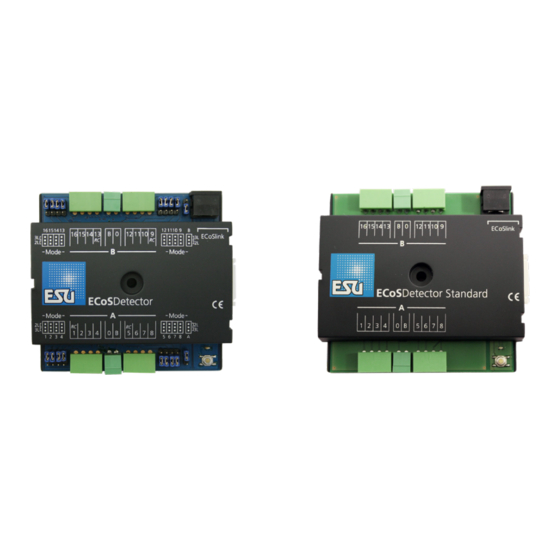
ECoSDetector
Instruction manual
1 . E d i t i o n , J u n e 2 0 1 1
50094 ECoSDetector
50096 ECoSDetector Standard
P/N 03811-10659
Table of
Contents
Previous
Page
Next
Page
1
2
3
4
5
Advertisement
Table of Contents
Need help?
Do you have a question about the ECoSDetector and is the answer not in the manual?
Ask a question
Questions and answers
Related Manuals for Esu ECoSDetector
Network Hardware Esu 50094 Instruction Manual
(16 pages)
Network Hardware Esu 50096 Instruction Manual
(16 pages)
This manual is also suitable for:
Ecosdetector standard
50094
50096
Table of Contents
Save PDF
Print
Rename the bookmark
Delete bookmark?
Delete from my manuals?
Login
Sign In
OR
Sign in with Facebook
Sign in with Google
Upload manual
Upload from disk
Upload from URL


Need help?
Do you have a question about the ECoSDetector and is the answer not in the manual?
Questions and answers