Table of Contents
Advertisement
Quick Links
SA C 7-35
SA
SA
C 7-35
C 7-35
C 7-35 Air Da
SA
SA
C 7-35
Putting Power In Your Navigation System
Get The Most From Your Garmin GNS430/530
Real Time Winds Aloft
Density Altitude
Outside Air Temperature
Improved Roll Steering And Autopilot Capture
ADS-B Interface to Mode S Transponders
Photo Courtesy NASA Hubble
Air Da
Air Da ta Computer
Air Da
ta Computer
ta Computer
ta Computer
Air Da
ta Computer
SANDIA aerospace
SANDIA aerospace
SANDIA aerospace
SANDIA aerospace
SANDIA aerospace
Advertisement
Table of Contents

Summary of Contents for SANDIA aerospace SAC 7-35
- Page 1 Get The Most From Your Garmin GNS430/530 Real Time Winds Aloft Density Altitude Outside Air Temperature Improved Roll Steering And Autopilot Capture ADS-B Interface to Mode S Transponders SANDIA aerospace SANDIA aerospace SANDIA aerospace SANDIA aerospace SANDIA aerospace Photo Courtesy NASA Hubble...
- Page 2 YSTEMS A full featured Air Data Computer enhancing the utility of your navigation system. The SAC 7-35 provides all the performance of Airdata Computers costing thousands of dollars more. Altitude In-Flight Monitoring (AIM) alerts the pilot whenever the aircraft deviates more than 100’...
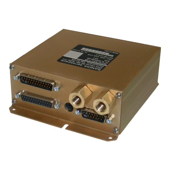
- Page 3 SAC 7-35 Airdata Computer Installation Manual SANDIA aerospace, Inc. SANDIA aerospace, Inc. SANDIA aerospace, Inc. SANDIA aerospace, Inc. SANDIA aerospace, Inc. 3700 Osuna Rd. NE, Suite 711 Albuquerque, NM 87109 305586-00 www.sandia.aero...
-
Page 4: Record Of Revisions
This document and the information contained herein is the proprietary data of SANDIA aerospace, Inc. No part of this document may be transmitted, reproduced, or copied in any form or by any means without the prior written consent of SANDIA aerospace, Inc. Due to SANDIA aerospace’s continued product and quality improvement programs, information contained in this document is subject to change without prior notice. -
Page 5: Table Of Contents
1.1 Introduction ........................4 1.1.1 Product Description .................... 4 1.2 Technical Characteristics ....................5 1.2.1 Physical Characteristics ..................5 1.2.1.1 SAC 7-35 ..................... 5 1.2.1.2 STP 78 OAT Probe ..................5 1.2.2 Operational Characteristics ................... 5 1.2.3 Operating Limitations ..................5 1.2.4 Outputs ....................... -
Page 6: List Of Illustrations
6 Pin Din to Serial Interconnect ................24 Figure 4-2 RS-232 Status Lines Setting ................... 26 Figure 4-3 SAC 7-35 Configuration Mode - Unit Trim Status ........... 26 Figure 4-4 SAC 7-35 Configuration Mode - Fuel Unit Status ........... 26... -
Page 7: Section 1 General Description
The SAC 7-35 is a solid state -1000 to 35,000 foot airdata computer and altitude encoder. With the addition of a fuel flow transducer(s), the SAC 7-35 will also provide fuel flow data to systems capable of displaying that information. The SAC 7-35 provides five data outputs that allow it to interface with a wide range of transpon- ders, TAWS, MFD’s, Navigation Systems and a variety of other avionics products. -
Page 8: Technical Characteristics
1.2 TECHNICAL CHARACTERISTICS 1.2.1 Physical Characteristics 1.2.1.1 SAC 7-35 Width: 4.87” (5.11” with mounting tray) Height: 1.89” (2.35” with mounting tray) Depth: 5.62” (5.62” with mounting tray) Weight: 1.18 lbs. (1.39lbs. with mounting tray) 1.2.1.2 STP 78 OAT Probe See Fig 3.3 for Dimensions Weight: .067 lbs... - Page 9 Indicated Airspeed: 0-450 KTS 0.088-.999 MACH Accuracy Accuracy MACH Number Accuracy MACH Tolerance 0.3 to 0.4 0.012 .0.5 0.010 0.0075 0.7-0.9 0.0050 0.0075 True Airspeed Accuracy TAS Accuracy 10000 10000 10000 10000 10000 10000 30000 10.1 30000 30000 30000 305586-00...
-
Page 10: Operating Limitations
King D. Each of these output formats work with ‘Aviation’ format input. The SAC 7-35 will also interface to a Garmin ADS-B serial output on port -B at 9600 baud. When connected to ADS-B input no serial data is output on port-B. -
Page 11: Rs 232 (C And D) Corresponding Altitude Output
1.2.4.1.2 RS 232 (C & D) Corresponding Altitude The SAC 7-35 supports Garmin and Garmin AT RS232 Corresponding Altitude formats. Baud Rate Installation Configurable to 1200, 9600, 19200 or 38400 Data Bits Stop Bit Parity None Output Rate: 1 +/- .2 seconds Altitude Resolution 10”... -
Page 12: Gillham Grey Code Output
1.2.4.3 Gillham Grey Code Outputs a. 10 Bits available: D4, A4, A2, A1, B4, B2, B1, C4, C2, C1 b. Bit On Impedance: Less than 5 ohms c. Bit Off Leakage: Less than 10uA d. Maximum Current per bit: 20 mA e. -
Page 13: Figure 1-2 Sac 7-35 Environmental Qualification Form
Environmental Qualification Form for the SAC 7-35 Airdata Computer NOMENCLATURE: SAC 7-35, Airdata Computer TYPE/MODEL/PART NO: SAC 7-35 / 305548-00 TSO NUMBER: C88a, C106 MANUFACTURER’S SPECIFICATION AN/OR OTHER APPLICABLE SPECIFICATION: SAC 7-35 INSTALLATION MANUAL P/N 305586-00 QUALIFICATION TEST PLAN, 901000-QTP... -
Page 14: Figure 1-3 Oat Probe Environmental Qualification Form
NOMENCLATURE: Outside Air temperature Probe TYPE/MODEL/PART NO: STP 78 OAT Probe /305561-01 TSO NUMBER: C88a, C106 MANUFACTURER’S SPECIFICATION AN/OR OTHER APPLICABLE SPECIFICATION: SAC 7-35 INSTALLATION MANUAL P/N 305586-00 QUALIFICATION TEST PLAN, 901000-QTP MANUFACTURER: SANDIA AEROSPACE ADDRESS: ALBUQUERQUE, NM 87109 REVISION & CHANGE NUMBER OF DO-160: REV E... -
Page 15: Installation Considerations
35 must be configured with the transducer(s) K-factor number. If the aircraft has an altimeter with a 5 VDC baro pot, the SAC 7-35 can use this to provide corrected altitude output on the ARINC 429 bus. The Garmin-Z output format does not support Baro Correction information. -
Page 16: Mounting Considerations
7-35 to the altimeter. Be sure to allow an ample service loop on the cable to allow for calibra- tion of the SAC 7-35. You’ll notice that the SAC 7-35 mounting tray has the same hole pattern as the SAE 5-35 encoder. This will simplify installations where the SAE 5-35 is being up- graded with the SAC 7-35. -
Page 17: General
The mounting hole pattern for the SAC 7-35 mounting tray contains five holes. For new instal- lations, it is recommended that the four corner holes be used to mount the SAC 7-35 tray. The fifth hole has been added to facilitate upgrades from some manufactures encoders. Refer to the SAC 7-35 tray dimensions in Figure 3-1 to determine if the hole pattern of the removed system match the hole pattern of the SAC 7-35 mounting tray. -
Page 18: Figure 3-1 Mounting Tray Dimensions
Figure 3-1 Mounting Tray Dimensions 5.48 4.98 P200 J100 P101 J104 Figure 3-2 Unit Outline Dimensions 305586-00... -
Page 19: Static And Pitot Port Connection
STATIC AND PITOT PORT CONNECTION Standard 1/8 - 27 NPT brass fittings are provided on the front plate of the SAC 7-35 for attach- ing to the aircraft static and pitot systems. An adapter may be used to convert these to match the aircraft static and pitot plumbing. -
Page 20: Electrical Installation
Power can be supplied from the aircraft buss through a 2 Amp circuit breaker. Since the SAC 7-35 is TSO’d as an encoder, power can also be supplied from the onboard transponder. If power is supplied from the transponder, the SAC 7-35 and it’s airdata functions will not operate if the transponder is turned off or removed from the aircraft. -
Page 21: Fuel Flow Interconnect
FUEL FLOW INTERCONNECT The SAC 7-35 accepts Fuel Flow from a pulse type fuel flow transducer, such as the Flow Scan 201 series, that outputs flow rates from 0-14400 GPH (2000 pulses/sec max). The SAC 7-35 can use existing Fuel Flow transducers that are already installed in the aircraft, if they are of the proper type. -
Page 22: Transponder Interconnect
2. The transponder provides a switched ground enable signal. 3. The transponder provides a strobe-ground enable signal. The SAC 7-35 is compatible with all three systems. Refer to the appropriate transponder installation manual for detail. Interconnect information for the most popular transponders can be found in Figure 3-7. -
Page 24: Figure 3-8 Sac 7-35 Interconnect Wiring Diagram
Note 4 NC 22 Figure 3-8 SAC 7-35 Interconnect Wiring Diagram... - Page 25 Installation Notes: Note 1: All wires are 24 AWG or larger unless otherwise noted. Note 2: Ground Strobe output to P101-6 if not required for transponder. Note 3: Fuel Flow transducers should never have power connected to two sources. This will cause damage to one of the devices.
-
Page 26: Figure 3-9 Front Panel Connector Location
AIM SW In AIM SET Reserved (+8V) Reserved (-8V) AIM ALT Note 1 Internally Connected Note 2 Ground Pin 7 if Baro Pot not connected Note 3 Ground Strobe Pin is not Figure 3-8 required by Transponder SAC 7-35 Pinout... -
Page 27: Configuration And Calibration
4.1 Setup for Configuration The SAC 7-35 has a configuration mode allowing it to be configured for varying aircraft equipment. A DIN to 9-pin serial port adapter can be plugged into the configuration connector, J104 (a 6 pin Din to 9 Pin serial adapter cable, SANDIA upart number 305580, is supplied with each unit).The SAC 7-35 automatically senses... - Page 28 Note: The SAC 7-35 must be reset by cycling power, after configuration is completed The configuration menu presents all the adjustable parameters. To change a parameter enter a single character followed by return. For example: <enter> Select an Option to Configure: 1 Select the number 1 and press Enter.
-
Page 29: Status Line Descriptions
(ft) Trim >> Alt: -1270:1270 IAS: 0 :10 Baro : -1.27 : 1.27 OAT: . 0 : .0 Hdg: 000:0 Figure 4-3 SAC 7-35 Configuration Mode - Unit Trim Status Fuel Density/Type Setting Fuel Startup Delay/Ignore Time (sec) Fuel K-Factor Left Right Fuel >>... -
Page 30: Serial Port Settings
Parameter Descriptions 4.3.1 Serial Port Settings Parameter Description Allowed Settings 1. Port 1 Format Set Port 1 (RS232A) Data Format Garmin-Z King-D Garmin-G Disable 2. Port 1 Baud Set Port 1 (RS232A) Baud Rate 1200 bps 9600 bps 19200 bps 38400 bps 3. -
Page 31: Synchro Input Settings
4.3.4 Altitude Trim The altitude trim adjusts all of the SAC 7-35 encoder altitude output including: the Gillham Grey code and serial encoder.. There are two trim values, high trim and low trim. The low trim value is applied for sea level altitudes. -
Page 32: Fuel Flow Configuration And K-Factor
Parameter Descriptions Con’t 4.3.7 Fuel Flow Configuration and K-factor Parameter Description Allowed Settings d. Fuel Start-up delay Delay Fuel Flow Calculation (0-12 for 0-60 second delay) e.Fuel Input Engine count 0 ,1,2 Fuel Density 0 = 100LL 1 = Jet B 2 = Jet 1A 3 = JetA or enter #... -
Page 33: Oat Probe Trim
4.3.10 OAT Probe Trim The OAT probe trim should always be set to 0 for SAC 7-35 installations with the Sandia Aerospace OAT Probe (305561-01). Parameter Description Allowed Settings o. OAT Probe Outside Air Temperature Trim +/-127 0.05 Enter high and then low trim offsets Continued Airworthiness The encoder portion of the SAC 7-35 requires calibration every 24 months per FAR 91.411. - Page 34 SAC 7-35 Airdata Computer...
- Page 35 We will show you why a GA pilot would benefit from installing an Airdata Computer and why the Sandia SAC 7-35 is the right choice. We will concentrate on installations with the Garmin 400/500 series units (there are approximately 100,000 of the Garmin 400/500 series navigators in operation, a great sales and marketing opportunity).
- Page 36 With the SAC 7-35 Without the SAC 7-35 The SAC 7-35 is supplied with an OAT (Outside Air Temperature) probe and provides the temperature information to the navigator. On the Aux page, the pilot can monitor the OAT to determine when he is entering icing conditions.
Need help?
Do you have a question about the SAC 7-35 and is the answer not in the manual?
Questions and answers