
Summary of Contents for Johnson T3XM
- Page 1 Issue Date 2018/4/8 Edition Doc No. JOHNSON Edition Revision Date Page Time Johnson Industries (Shanghai) Co., Ltd T3XM Console Service Manual Approval Review Editor Kyle Schweitzer Jerry Zhu...
-
Page 2: Table Of Contents
..........................1 1.1 Console Overview ....................2 1.2 Serial Location/Model Type Apply List ......................3 CHAPTER 2: CONSOLE INSTRUCTION ........................3 2.1 T3XM Console Description CHAPTER 3: CONSOLE SPECIAL MODE ..........................5 3.1 Special Mode Browse ............................6 3.2 Manage Mode ............................7 3.3 Engineer Mode ............................ -
Page 3: Chapter 1: Serial Number Location
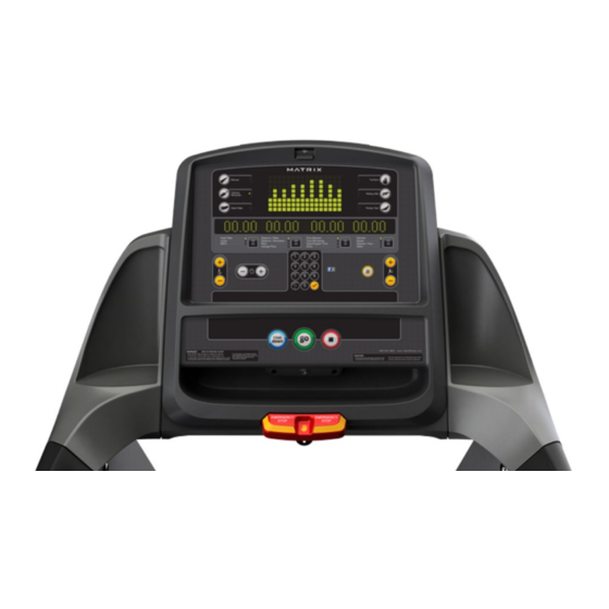
CHAPTER 1 : SERIAL NUMBER LOCATION CHAPTER 1: SERIAL NUMBER LOCATION 1.1 Console Overview T3XM... -
Page 4: Serial Location/Model Type Apply List
CHAPTER 1 : SERIAL NUMBER LOCATION 1.2 Serial Location/Model Type Apply List CHAPTE 2: Troubles... -
Page 5: Chapter 2: Console Instruction
CHAPTER 2 : CONSOLE INSTRUCTION CHAPTER 2: CONSOLE INSTRUCTION 2.1 T3XM Console Description The Matrix machine is inspected before it is packaged. It is shipped in two pieces: the base and the console. Carefully unpack the unit and dispose of the box material. Note: There is a thin protective sheet of clear plastic on the overlay of the console that should be removed before use. - Page 6 CHAPTER 2 : CONSOLE INSTRUCTION N) BELT DIRECTION: Press to change belt direction from forward to reverse. O) USB PORT: Used for software updates only.
-
Page 7: Chapter 3: Console Special Mode
CHAPTER 3 : CONSOLE SPECIAL MODE CHAPTER 3: CONSOLE SPECIAL MODE 3.1 Special Mode Browse Mode Name Method Programmer List Manage mode “√” + “1001” + “√” Engineer mode “√” + “2001” + “√” Special Mode Refer to below picture Service mode “√”... -
Page 8: Manage Mode
CHAPTER 3 : CONSOLE SPECIAL MODE 3.2 Manage Mode Category Name Default Range Maximum Time 4-99 Default Time 4-max Workout Default level 1-10 Pause Time 5:00 00:30/1:00/2:00/3:00/4:00/5:00 10-100 Weight 150lb/68kg 50lb/23kg-400lb/182kg User 72/183(inch/cm, Default height 36/91-96/244 1inch=2.54cm) Gender male Male/female Date 10-100 Date &Time... -
Page 9: Engineer Mode
CHAPTER 3 : CONSOLE SPECIAL MODE Category Name Default Range Disable/Enable Disable/Enable Shows the actual MAC ID MAC address Shows the actual IP address AP Mode ON/OFF Internet Export setting to USB Export Wi-Fi setting to USB Import setting from Import Wi-Fi setting to USB Signal strength Disconnected/25%/50%/75%/100%... -
Page 10: Service Mode
CHAPTER 3 : CONSOLE SPECIAL MODE 3.4 Service Mode Category Name Default Range Distance 0~999999 Mile/Km Accumulate Time 0~999999 Hours Error --Display None Error0~Error10/None --Reset Headphone Jack Sensor --0~999999 --Insert Counts --Clear log in times --Reset Export to USB Configuration Import from USB Factory Default Reset... -
Page 11: Chapter 4: Troubleshooting
CHAPTER 4 : TROUBLESHOOTING CHAPTER 4: TROUBLESHOOTING 4.1 Electrical Diagram T3XM Electrical Diagram... -
Page 12: Ports Description
CHAPTER 4 : TROUBLESHOOTING 4.2 Ports Description MCB introduction T3XM UCB PORTS DESCRIPTION UCB Front side Heart Rate Interface digital Quick Key/Earphone/HRT TV power CN10 TV Keypad JTAG1 CN11 Main Key UCB STATUS CN12 C-SAFE/TV Overlay LED CN13 SAFEKEY CN14... -
Page 13: Error Code List
CHAPTER 4 : TROUBLESHOOTING 4.3 Error Code List 4.3.1. Speed Errors Error Code Description Class Level 0040 Roller RPM sensor - no speed response of roller. After setting speed on the console, speed cannot reach the target in 0041 60 seconds. (Speed too low) After setting speed on console, speed cannot reach the target in 60 0042 seconds. - Page 14 CHAPTER 4 : TROUBLESHOOTING Error Code Description Class Level 02A2 Over DC bus voltage 02A3 Over voltage limited in DC bus 02A4 U phase current sensor and circuit fail 02A5 V phase current sensor and circuit fail 02A6 W phase current sensor and circuit fail 02A7 Over Irms of phase current of motor 02A8...
-
Page 15: Ucb Error
CHAPTER 4 : TROUBLESHOOTING 4.3.3. UCB Error Error code Description Class Level 0301 Memory block fail (Flash, EEPROM ) 0302 UCB low battery voltage 0303 UCB low supply voltage 0304 Earphone board needs to replace 0305 USB Hardware OT or OC 0306 Keypad press keep 60 seconds 0307... -
Page 16: Communication Errors
CHAPTER 4 : TROUBLESHOOTING 4.3.4. Communication Errors Error code Description Class Level 通訊接收逾時 ( 起始 byte 至結束 byte 之間逾時 ) 0440 Timeout for receiving communication packet 通訊命令格式正常 , 但無法執行該命令 0441 Correct format of communication command but LCB could not execute the command The received command code from the console is correct and is 0442 supported, but it has less or more data arguments... -
Page 17: Console Does Not Light Up
CHAPTER 4 : TROUBLESHOOTING 4.4 Console Does Not Light Up SYMPTOM: When the power switch is ON, the console does not turn on. Which means the console is damaged or the console cable is not connected properly. The poor connection to the terminals on the lower control board. The lower control board is damaged. -
Page 18: Keypad/Heart Rate
CHAPTER 4 : TROUBLESHOOTING 4.6 Keypad/Heart Rate SYMPTOM: The Keypad has no reaction /The Keypad function does not match screen display. The screen cannot display heart rate pulse SOLUTION: 1. The console cable is connected improperly. Remove the console mast and check to see if the console upper cable and console lower cable are connected well. -
Page 19: Wifi Issue
CHAPTER 4 : TROUBLESHOOTING 4.8 WIFI Issue 1. Use mobile phone or portable device search router SSID and login (Fig. 1) 2. Use the SPEEDTEST App. to measure upload and download speed. It is normally up to 64kB or higher, depends on local ISP (internet service provider) but 0kB means fail to connection. -
Page 20: Chapter 5: Main Component Installation
CHAPTER 5 : MAIN COMPONENT INSTALLATION CHAPTER 5: MAIN COMPONENT INSTALLATION 5.1 . Wi-Fi Module Install 5.1.1.Wi-Fi module Install 1) Prepare Wi-Fi Module : Wi-Fi module; HF-A11-0;(Fig. 1) 2) To loose 2 pcs of screws already in Wi-Fi Module socket (Fig. 2) 3) Take the Wi-Fi Module and Push Wi-Fi module into socket carefully (Fig. -
Page 21: Wi-Fi Setup
CHAPTER 5 : MAIN COMPONENT INSTALLATION 5.1.3. Wi-Fi setup 1) Power on 2) Press “enter” key 3 seconds and display “CSAFE OK”. (Fig. 1) 3) Press“( - ) ” key back to previous menu. (Fig. 2) 4) Press speed up “ + “ key and choice Wi-Fi” function (Fig. 3) 5) Press “enter“...
Need help?
Do you have a question about the T3XM and is the answer not in the manual?
Questions and answers