Table of Contents
Advertisement
Quick Links
TRIANGLE BIOMEDICAL SCIENCES, INC.
3014 CROASDAILE DRIVE • DURHAM, NC 27705-2507 • USA • 919.384.9393 • FAX 919.384.9595 • E-MAIL: tbs@trianglebiomedical.com
ATP ™ Tissue Processor
Catalog # ATP1-120, ATP1-220
Operations Manual
Version 5.3, May 2006
Be certain to read this manual thoroughly
before proceeding with unpacking and installation.
www.trianglebiomedical.com
INNOVATIONS FOR SCIENCE ™
Advertisement
Table of Contents

Related Manuals for tbs electronics ATP1-120


Summary of Contents for tbs electronics ATP1-120
- Page 1 TRIANGLE BIOMEDICAL SCIENCES, INC. 3014 CROASDAILE DRIVE • DURHAM, NC 27705-2507 • USA • 919.384.9393 • FAX 919.384.9595 • E-MAIL: tbs@trianglebiomedical.com ATP ™ Tissue Processor Catalog # ATP1-120, ATP1-220 Operations Manual Version 5.3, May 2006 Be certain to read this manual thoroughly before proceeding with unpacking and installation.
- Page 2 WELCOME Thank you for selecting the ATP™ Automated Tissue Processor. This instrument was carefully designed to be easy to use, safe to operate and capable of producing consistent, quality results. The embedded Personal Computer affords you the flexibility and reproducibility required by the modern laboratory.
-
Page 3: Table Of Contents
TABLE OF CONTENTS INTRODUCTION .....................1 CHAPTER 1 – GENERAL INFORMATION..............2 1.1 – Regulatory Compliance ..................2 1.2 – Patents, Trademarks and Specifications ............2 1.3 – Symbols and Conventions ................3 1.4 – Abbreviations and Units of Measure...............4 1.5 – Safety Precautions ..................5 CHAPTER 2 –... - Page 4 7.6 – Hour and Date ....................23 7.7 – Purge Reagents Limits Setting ..............23 7.8 – CCW (Paraffin Oven) Temperature Setting..........24 7.9 – Charcoal Filter Limit Setting .................24 7.10 – WPC (Wax Purification Cycle) ..............25 Activation / Deactivation ..................25 7.10.1 – Manual Start of the WPC.................26 7.11 –...
- Page 5 10.3 – Selecting a Program ...................42 10.4 – Setting the Program Completion Time/Date ..........43 Setting Delay......................44 Programming Completion Times................44 Midweek holidays....................45 Starting from step other than the first..............45 Runtime Test Aborting Run ................45 10.5 – Starting a Procedure...................46 10.6 – Interrupting the Process ................47 10.7 –...
- Page 6 25 - DRAIN TIME OUT..................57 26 - RET. NOT EMPTY..................57 27 - OVER FILL P ....................57 30 - COM ERROR [FRAME] ................57 31 - COM ERROR [PARITY]................57 32 - COM ERROR [OVERRUN].................58 33 - COM ERROR [TIMEOUT] ................58 39 - COM ERROR [LINE OR PORT DOWN] .............58 40 - ELODEV LACK ...................58 50 - OVER PRESSURE ..................58 51 - OVER VACUUM ..................59...
- Page 7 15.2 – Remote Alarm and Auto-dialer ..............69 APPENDIX 1 – ACCESSORIES AND SPARE PARTS..........70 APPENDIX 2 – ATP™ TECHNICAL DATA SHEET..........71 APPENDIX 3 – ATP™ FEATURES ...............72 APPENDIX 4 – ATP™ PROGRAM MENU FLOW ..........73 CONTACT INFORMATION ...................74...
-
Page 8: Introduction
INTRODUCTION ™ Thank you for purchasing an ATP . The instrument was designed by experienced engineers with the input of service and laboratory technicians. The number one priority was to produce the most dependable tissue processor on the market. After ®... -
Page 9: Chapter 1 - General Information
CHAPTER 1 – GENERAL INFORMATION Before using the instrument, please make certain that you carefully read this manual. Pay particular attention to the precautions that must be taken for user and product safety. ™ The ATP is an automatic tissue processor for laboratory use. It should only be used for routine processing of histological tissue samples. -
Page 10: Symbols And Conventions
under Patent # US 6,780,380 B2. 1 . 3 – S Y M B O L S A N D O N V E N T I O N S Do not use free flame near the instrument No smoking near the instrument Recyclable High voltage Important safety notice... -
Page 11: Abbreviations And Units Of Measure
1 . 4 – A B B R E V I A T I O N S A N D N I T S O F E A S U R E BBREVIATIONS Analog/Digital Converter Paraffin Wax Heating Chamber Retort (Processing Chamber) Control Module Main Valve Air Pump... -
Page 12: Safety Precautions
1 . 5 – S A F E T Y R E C A U T I O N S Carefully follow the installation instructions: • Severe damage can result if the instrument is connected to a power supply different from that stated in the manual and on the identification tag at the rear of the instrument. - Page 13 • Due to the presence of flammable substances inside reagent bottles, it is recommended to: Avoid smoking near the instrument. Avoid using open flames near the instrument (e.g. Bunsen burner). • DO NOT wear clothes that are prone to create electrostatic charges while handling reagents (wool, synthetic fibers, etc.).
-
Page 14: Chapter 2 - Unpacking, Packing And Transporting
CHAPTER 2 – UNPACKING, PACKING AND TRANSPORTING Before moving or transporting the instrument, it is essential to carefully read this chapter, paying particular attention to the instrument setup instructions. The warranty is invalid if the instrument is improperly operated. Be certain to follow the instructions and recommendations provided by this manual. -
Page 15: Packaging And/Or Preparation For Transport
2 . 2 – P A C K A G I N G A N D R E P A R A T I O N F O R R A N S P O R T To transport the instrument, perform the following steps: 1) Remove all reagents (paraffin included) from their bottles. -
Page 16: Chapter 3 - Introduction To The Atp Processor
™ CHAPTER 3 – INTRODUCTION TO THE ATP PROCESSOR 3 . 1 – G E N E R A L E A T U R E S • The ATP ™ tissue processor recycles the air utilized to move the reagents to and from the Retort. -
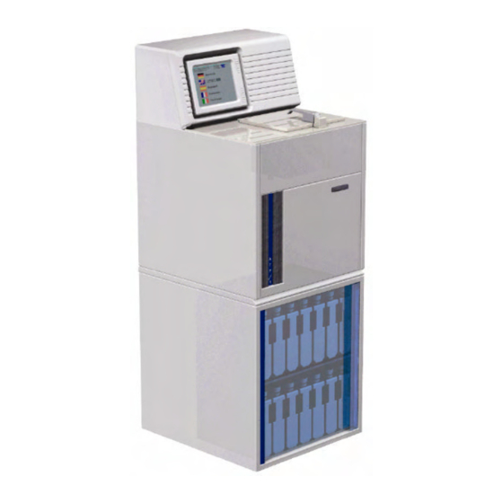
Page 17: Front View
3 . 2 – F R O N T I E W Tilting color touch screen Floppy Retort drive Heated paraffin chamber (5 bottles) Reagent bottle chamber Charcoal filter bottles... -
Page 18: Rear Panel & Floppy Drive
3 . 3 – R & F E A R A N E L L O P P Y R I V E On the rear panel of the control module there are: A = On/Off main switch B = Main power connection module C = Fuse holder (2 x 10A fuses) D = Keyboard Connector (for use by service technicians) E = Remote Alarm socket:... -
Page 19: Chapter 4 - Reagents
CHAPTER 4 – REAGENTS 4 . 1 – C O M P A T I B L E E A G E N T S ™ The following reagents can be utilized in the ATP without any risk of damage: •... -
Page 20: Incompatible Reagents
4 . 2 – I N C O M P A T I B L E E A G E N T S Below is a short list of well-known reagents that CAN DAMAGE the instrument. This list is NOT complete. Before using reagents not explicitly noted in this manual, ®... -
Page 21: Chapter 5 - Installation And Operational Qualification
CHAPTER 5 – INSTALLATION AND OPERATIONAL QUALIFICATION This procedure describes the steps for installation and testing of the basic mechanics of the unit and should be done on all new units or units returning from factory service. 1. Position the unit on a flat level surface away from heat (radiators, stoves, direct sunlight, etc.) and moisture (sinks, drains, etc.). - Page 22 8. From the Main screen select Service/ Vacuum Test. Perform a vacuum test to confirm the operation of the pumps and sensors associated with the vacuum system. 9. From the Main screen select Service/ Retort Heating. Perform a Retort heating test.
-
Page 23: Chapter 6 - Preparation For Operation
CHAPTER 6 – PREPARATION FOR OPERATION 6 . 1 – F I L L I N G E A G E N T O T T L E S The emptying and subsequent refilling of reusable reagent bottles must be done in accordance with all safety regulations for handling flammable and toxic substances. -
Page 24: Filling Paraffin Bottles
6 . 2 – F I L L I N G A R A F F I N O T T L E S ™ The ATP tissue processor is unique in that the same bottles are used for paraffin and reagents. Paraffin bottles are placed in a special heating chamber that maintains a constant temperature of (54-60°... -
Page 25: Installing Charcoal Bottles
Paraffin waxes tend to leave residues that, if not removed, may cause damage to the instrument. Regular paraffin changes are essential for optimum processor performance. WARNING: Never leave a slot without a bottle; the bottles should always stay in their slots with their normal paraffin level of 2.5 lt. The absence of one bottle may cause an incorrect heating of the other bottles. -
Page 26: Chapter 7 - First Run Programming
CHAPTER 7 – FIRST RUN PROGRAMMING 7 . 1 – I N T R O D U C T I O N Prior to running the unit for the first time, there are a number of custom settings that should be set by the Supervisor. •... -
Page 27: Main Menu
7 . 3 – M A I N E N U This is the Main Menu: Software Version Menu Name Reagent Management System (RMS) Status Wax Purification Cycle (WPC) Status Process Counter Charcoal Filter Status Retort Temperature Wax Oven Temperature Retort Pressure At the bottom of the screen are buttons used for navigation: ENTER Data confirmation, process starting, menu selection, etc. -
Page 28: Reagent Labels
7 . 4 – R E A G E N T A B E L S From the Main Menu, select SETUP to access the Setup Menu. Choose REAGENT LABEL. Reagent names must be defined before they can be used in a program. Up to 12 different reagent names can be defined. -
Page 29: Program Label
7 . 5 – P R O G R A M A B E L Program names must be defined before the program can be defined or edited. Up to 12 different program names can be defined. Use ↑and ↓ arrows to select the position (name) you wish to edit. Use ←... -
Page 30: Hour And Date
7 . 6 – H O U R A N D A T E Select HOUR and DATE from the Setup Menu. The Hour and Date Screen: With the arrow keys, point the cursor at what is to be changed, then increase or decrease its values with the + and - keys. -
Page 31: Ccw (Paraffin Oven) Temperature Setting
Please note: if the user desires to replace the Purge reagents before their counter reaches the preset limit, it will be necessary to reset the counter by the “Zero Resetting Single Counter” function. 7 . 8 – C C W ( P A R A F F I N V E N E M P E R A T U R E... -
Page 32: Wpc (Wax Purification Cycle)
If you are operating the ATP™ in an area with high relative humidity, if you run long processes frequently, if you apply pressure and/or vacuum to most or all of the process steps, if you agitate the reagents in the retort frequently, and especially if several of these factors apply to your usage, it will be necessary to set your process number limits for the charcoal filters at or below the minimum values mentioned above. -
Page 33: Manual Start Of The Wpc
Deactivation of the WPC is advisable when: • An excessive consumption of the charcoal filters makes its use less than economical for the user. This could occur due to a combination of the environmental and usage factors mentioned above. • The instrument is malfunctioning frequently. Discontinuing use of the WPC lowers the workload on the ATP™... -
Page 34: Chapter 8 - Programming Processes
CHAPTER 8 – PROGRAMMING PROCESSES 8 . 1 – P R O G R A M M I N G R O C E S S E S To define new or edit existing programs, the Program Label must exist, and any reagents to be included in the program must already be defined. -
Page 35: Reagent
When in the field to edit or change, use keys to change values. Press ENTER to save changes and to go back to the previous menu. Press ESC to abort the operation and to go back to the previous menu. R e a g e n t Reagent names are labels prepared in advance. -
Page 36: Agit
A g i t ™ The reagent agitation in the ATP is accomplished by bubbling air up from the bottom of the Retort. Select from the following frequencies: 0 = no agitation 1 = an agitation every 30 minutes 2 = an agitation every 20 minutes 3 = an agitation every 15 minutes 4 = an agitation every 10 minutes 5 = an agitation every 5 minutes... -
Page 37: Chapter 9 - Reagent Management System (Rms)
CHAPTER 9 – REAGENT MANAGEMENT SYSTEM (RMS) 9 . 1 – I N T R O D U C T I O N The ATP RMS is a system to punctually and exactly manage all reagents to ™ enhance processing consistency and improve sample quality. The use of the Reagent Management System provides quality assurance documentation of reagent bottle status. -
Page 38: Choosing The Rms Mode
9 . 2 – C R M S M H O O S I N G T H E O D E This will allow you to select either of the following two functions: • Single Bottle mode: In Single Bottle mode, each bottle is managed as a separate entity, therefore, each bottle will have a defined limit usage and will be defined by the specific type of reagent it contains. -
Page 39: Rms Single Mode Description And Example
9 . 2 . 1 – R M S S I N G L E O D E E S C R I P T I O N A N D X A M P L E The RMS – Instructional Screen indicates what action to take. As explained in previous sections, at the end of each process and after the completion of the WPC (when active), the Reagent Management System will activate a screen like the one shown above. -
Page 40: Rms Group Mode Description And Example
Conversely, if the RMS has been regularly executed, any request for execution from the Main Menu will be denied. 9 . 2 . 2 – R M S G R O U P O D E E S C R I P T I O N A N D X A M P L E This mode facilitates maintenance, management and quality assurance by: •... -
Page 41: Example Group Mode Sequence
E x a m p l e G r o u p M o d e S e q u e n c e High grade dehydrants are placed in bottles 6, 7 and 8. The limits of this group are fixed as 1 process. The sequence of use would be the following: SAGE PROCESS # 1... - Page 42 The processing results will be the ultimate indicator as to whether the RMS settings are ideal. To correct inadequate infiltration replace all the reagents, use the counters reset functions to set the group counters to zero and decrease the process/cassette number limits.
-
Page 43: Rms - Programming Reagents Definition
9 . 3 – R M S – P R O G R A M M I N G E A G E N T S E F I N I T I O N Defining reagents allows the operator to identify the type of reagent that is utilized in any single bottle. -
Page 44: Rms - Programming Limits Definition
• Between one group and another there could be bottles of undefined content that therefore are not managed by the automation of the RMS. This, however, is unadvisable because it is inconsistent with the goals of the Histology process. • A group could consist of just one bottle (a typical example is the group of fixatives). -
Page 45: Rms - Counters Total Reset
When defining the process number/cassette number limits for groups of reagents, the same factors that were considered when assigning single bottle limits will be considered here. The difference is that when the preset limit for the group is reached or exceeded, the RMS will require the substitution of the bottle whose reagent is the most polluted (the bottle in the group that, in the previous processes, was used first). -
Page 46: Rms On / Off
9 . 6 – R M S O This function will turn the RMS on or off. Changing the RMS mode will reset the counter to zero. Again, it is recommended that all reagents be replaced prior to changing the RMS mode. 9 . - Page 47 A printout of the RMS status can be useful if there is some question about the cycle of reagent substitution or if there is some other reason to refresh or exchange some reagents and reset their process/cassette number counters. Finally, although the user is asked at the end of each process if they would like to print a report of the process just performed, it can also be printed from this menu.
-
Page 48: Chapter 10 - Normal Operation
CHAPTER 10 – NORMAL OPERATION 1 0 . 1 – L O A D I N G A M P L E S I N T O T H E A S K E T The standard sample basket has 4 metal dividers and springs installed to allow cassettes to be organized and to prevent cassettes from opening during a run. -
Page 49: Selecting A Program
1 0 . 3 – S E L E C T I N G A R O G R A M Select START PROCESS from the MAIN menu. The screen now should look the same as the Edit Program screen. Use the ↑... -
Page 50: Setting The Program Completion Time/Date
1 0 . 4 – S E T T I N G T H E R O G R A M O M P L E T I O N I M E A T E The Start Process Screen: Two lines are displayed above the icons. -
Page 51: Setting Delay
S e t t i n g D e l a y Use the ← and → arrows to choose one of the fields which indicate hours, minutes and day of the week of the program completion. Use the + and - keys to change the time and date that the program is to end. The computer will automatically update the total processing time, the date of completion and the fields that indicate the amount of the delay expressed in days, hours and minutes. -
Page 52: Midweek Holidays
• Completion time cannot be set less than current time plus the time to complete process. For example, if you start a 12-hour program at 9:00pm and desire an end time of 7:30am, there is not enough time to complete the process without cutting its time short. -
Page 53: Starting A Procedure
1 0 . 5 – S T A R T I N G A R O C E D U R E After the date and time to complete a program has been entered, the program can be started by pressing ENTER. Use ESC to abort the operation and to go back to the main menu without starting the process. -
Page 54: Interrupting The Process
• The current step is highlighted and the time will count down until the step is complete. • Any alarms will appear in the window that displayed the program names in the sequence that the alarms occurred. • The first line in the message area will show the name of the current program and the scheduled date and time of completion. -
Page 55: Opening The Retort During A Program
1 0 . 7 – O P E N I N G T H E E T O R T U R I N G A R O G R A M There are some steps in which the retort CANNOT be opened and others in which the retort MUST NOT be opened. -
Page 56: Cleaning The Retort (Purge Cycle)
After the Retort empties, open the retort and take out the samples (if necessary, press the VACUUM RELEASE key). After removing the samples a message will appear asking the operator to authorize printing of the process report (if the printer is not present, or if a process report is not desired, it will be sufficient to press the ESC key to skip this operation). - Page 57 Purge Cycle procedure: The bottles containing the Purge Cycle reagents are labeled with P1 and P2 and must contain: (the first from the left, top row) (P1) xylene (or substitutes), the second (P2) 80% or 100% alcohol. The Purge Cycle reagent (if not managed by the RMS) must be changed at least every 5 completed paraffin processes.
-
Page 58: Chapter 11 - Alarms
CHAPTER 11 – ALARMS 1 1 . 1 – M A N A G I N G L A R M S There are two types of alarms: N o n - B l o c k i n g A l a r m s Alarms 1 through 9 are NON-BLOCKING alarms or WARNINGS that do not interrupt the program. -
Page 59: Non-Blocking Alarms
When uncertain as to the cause of the failure, have a qualified electrician check the line voltage for transient and/or drop-outs at the receptacle. If the alarm persists, ® call TBS technical assistance and do not use the instrument. 1 1 . 2 – N L O C K I N G L A R M S 1 - B L A C K O U T... -
Page 60: 2 - R E T O R T T ° L O W
2 - R E T O R T T ° L O W At the end of a step, (after the drain but before the start of the next step) the retort temperature is not at the value required by the program. This check is done only at the end of a stand-by step because it is not possible to know how much time is necessary for the reagent to reach the correct temperature. -
Page 61: 7 - F I L E N O T F O U N D
Cause – Excessive level of reagent in the bottle. Solution – Verify reagent levels. 7 - F I L E N O T F O U N D A file has not been found or an incomplete file has been found in the computer memory;... -
Page 62: Fill Time Out
1 2 - F I L L T I M E O U T The filling from a reagent or paraffin bottle has not occurred in the allotted time. Cause – See Alarm 11. Solution – See Alarm 11. 1 3 - O V E R F I L L S An overfill of reagent or paraffin has occurred in the Retort (detected by the overfill sensor). -
Page 63: File Not Found
Cause – The Rotary Valve motor has failed or the Rotary Valve position sensor has failed. Solution – No intervention by the user is possible. If the problem persists, ® contact the TBS service department for technical assistance 1 8 - F I L E N O T F O U N D An essential computer file is damaged or cannot be found and the error recovery system failed trying to correct the problem. -
Page 64: Drain No Press
Cause – The air pump or other pneumatic circuit parts have malfunctioned. Solution – No intervention by the user is possible. If the problem persists, ® contact the TBS service department for technical assistance. 2 4 - D R A I N N O P R E S S During the second phase of a drain, the pressure in the retort has not reached the correct value. -
Page 65: Com Error [Overrun]
Cause – See Alarm 30. Solution – See Alarm 30. 3 2 - C O M E R R O R [ O V E R R U N ] See Alarm 30. Cause – See Alarm 30. Solution – See Alarm 30. 3 3 - C O M E R R O R [ T I M E O U T ] See Alarm 30. -
Page 66: Over Vacuum
5 1 - O V E R V A C U U M See Alarm 50. Cause – See Alarm 50. Solution – See Alarm 50. 5 2 – P S B R E A K – H I G H Pressure Transducer problem. -
Page 67: Instrument Reset
1 1 . 5 – I N S T R U M E N T E S E T In the event the software has locked up and the instrument ceases operation, the software can be reset by the following procedure: On the rear of the instrument there is a green reset button. -
Page 68: Chapter 12 - Service Menu
CHAPTER 12 – SERVICE MENU 1 2 . 1 – E S E R E R V I C E E S T S The End-user Service Menu: EDIT SETUP V a c u u m t e s t The instrument will create a vacuum as if a program is running;... -
Page 69: Pressure Test
P r e s s u r e T e s t The instrument will create the pressure in the Retort as if a program is running; this test should be done with the retort empty. • The instrument should create a pressure between 1200 and 1250mBar (TP field) in a maximum time of 60 seconds (GRADIENT field). -
Page 70: Service Menu Abbreviation List
If there has been a power loss or the unit has been powered off and on, the alarm reset will need to be used to clear the Blackout Alarm. 1 2 . 2 – S E R V I C E E N U B B R E V I A T I O N I S T... -
Page 71: Chapter 13 - Safety Features
CHAPTER 13 – SAFETY FEATURES 1 3 . 1 – P R O T E C T I O N A G A I N S T V E R H E A T I N G The thermostat controls include a maximum temperature cutoff switch to prevent overheating of the paraffin chamber and Retort. -
Page 72: Chapter 14 - Instrument Maintenance
CHAPTER 14 – INSTRUMENT MAINTENANCE 1 4 . 1 – D A I L Y A I N T E N A N C E The daily maintenance of the instrument consists of: ü Cleaning the Retort ü Cleaning the Retort lid and gasket ü... -
Page 73: Charcoal Filters Replacement
• To maximize the value of this process and to therefore minimize paraffin consumption, the WPC should be run after every process. Important note: The retort should be cleaned (using the Purge Cycle following a process) prior to starting the WPC and the retort lid MUST remain closed during the purification cycle. -
Page 74: Fuse Replacement
1 4 . 6 – F U S E E P L A C E M E N T Fuse replacement should be done only by qualified personnel. Please note: Always disconnect the instrument! Never use fuses of a different rating and never try to repair damaged fuses. The ATP™... -
Page 75: Chapter 15 - Accessories
CHAPTER 15 – ACCESSORIES 1 5 . 1 – P R I N T E R The ATP™ is equipped with a serial port in the back panel for the connection of a ® printer. TBS offers a printer specifically for the ATP™ (cat # ATP1-P), or, any kind of serial printer with the following characteristics can be used: ü... -
Page 76: Remote Alarm And Auto-Dialer
1 5 . 2 – R E M O T E L A R M A N D U T O D I A L E R An automated dialer can be attached which will automatically dial a pre-set number if an alarm occurs during a run. -
Page 77: Appendix 1 - Accessories And Spare Parts
APPENDIX 1 – ACCESSORIES AND SPARE PARTS ESCRIPTION Accessories Auto Dialer ATP1-AD Printer (with: main power cord, serial cable, 1 paper roll, 1 ATP1-P ink ribbon, user manual) Charcoal filters 2/CS ATP-CFB Paraffin/reagent bottles (reusable, quick connector) 6/CS ATP1-BR Paraffin/reagent bottles (reusable, bottles only – no caps ATP1-123 or connectors) Screw caps for reagent bottles, solid 10/CS... -
Page 78: Appendix 2 - Atp™ Technical Data Sheet
APPENDIX 2 – ATP TECHNICAL DATA SHEET ™ Rating 220V, 50Hz; 110V, 60Hz Max power 1400 W Fuse 2x10A (5x20mm)+ 2x10A (6x25mm) Weight 120 Kg (264 lbs.) Dimension in mm (floor standing version) H 1338 - W 524 - D 600 Dimension in mm (table top version) H 770 - W 1048 - D 600 Height... -
Page 79: Appendix 3 - Atp™ Features
APPENDIX 3 – ATP FEATURES ™ Electronics Based on an industrial CPU with an Intel microprocessor Software language Microsoft C 6.00 Display 9.5” LCD - VGA mono tilting touch screen (panel-off feature to increase the life of the display and the display light) Shell (user interface) User friendly (Windows like) shell;... -
Page 80: Appendix 4 - Atp Program Menu Flow
APPENDIX 4 – ATP PROGRAM MENU FLOW ™... -
Page 81: Contact Information
CONTACT INFORMATION Customer service (919) 384-9393 (919) 384-9595 Triangle Biomedical Sciences, Inc. Mailing address 3014 Croasdaile Drive Durham, NC 27705 U.S.A. Sales and product information sales@trianglebiomedical.com service@trianglebiomedical.com Product Service questions info@trianglebiomedical.com All other inquiries Please visit us at http://www.trianglebiomedical.com...
Need help?
Do you have a question about the ATP1-120 and is the answer not in the manual?
Questions and answers