
Summary of Contents for Riegl LD90-3
- Page 1 LASER DISTANCE AND LEVEL METER LD90-3 USER'S MANUAL Version 9/01 CE Rev. 05-09-2001 (S 5.1) Rev. 18-09-2001 (S 5.1) Rev. 13-03-2002 (S 5.1) Rev. 19-03-2002 (S 5.1) Rev. 24-11-2005 (S 5.1) Rev. 16-06-2006 24/06...
- Page 2 In no event shall RIEGL LMS be liable for any loss of profit or any other commercial damage caused or alleged to have been caused directly or indirectly by this document.
-
Page 3: Table Of Contents
CONTENTS Short-form Description and Specifications.... 1 Safety and Reliability ..........11 Preparing for Measurement ........22 Mounting Instructions............. 22 Preparing the Power Supply ..........25 Fuse ..................26 Internal Grounding Scheme........... 26 Laser Safety Lock ..............27 Accuracy of Measurement ............. 27 Short Guidance for a Fast Start-Up ........ - Page 4 8.4.2 Unit - Speed Measurement ..........41 8.4.3 Measurement Time - Speed Measurement ....41 Hold Time................42 Distance Offset (Adjustment of the Reference Plane)..42 Data String Format..............43 Serial Baud Rate, Parity and Separator ........ 44 8.8.1 Baud Rate: ..............44 8.8.2 Parity: ................
- Page 5 8.19.6 Switching output - Message status value ...... 57 Serial Control Commands in Measurement Mode ................ 59 Start Programming Mode............59 Laser On ................59 Laser Off ................59 Trigger Measurement ............59 Trigger of RS232/RS422-Data Output, RS232/RS422 Inquiry Mode ................60 Clear RS232/RS422 Inquiry Mode ........
- Page 6 - IV -...
-
Page 7: Short-Form Description And Specifications
Dear Customer! We congratulate you on the purchase of the RIEGL LD90-3. You are now the owner of a high quality, optoelectronic measuring instrument. The instrument is easy to operate. However, we would ask you to take the time to carefully work through these operating instructions - especially the chapters 2 to 4 - before using the instrument. - Page 8 - 2 -...
- Page 9 Measurements can be taken to almost any surface regardless of the incident beam angle or surface characteristics Measurements are unaffected by the temperature of the material surface and of temperature gradients in the medium between the sensor and the target surface visit our webpage www.riegl.com - 3 -...
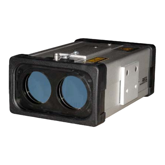
- Page 10 1 m - 150 m (3) 10pole socket for power supply, Data output: R S2 32 / RS4 22 4 -2 0 mA RIEGL Laser Measurement Systems GmbH A-3580 Horn AUSTRIA optional analog outputs, and switching output (4) Fuse holder...
- Page 11 Technical data are subject to change without notice , A-3580 Horn, Austria RIEGL Laser Measurement Systems GmbH Tel.: +43-2982-4211, Fax: +43-2982-4210, E-mail: office@riegl.co.at , Orlando, Florida 32819, USA RIEGL USA Inc. Tel.: +1-407-248-9927, Fax: +1-407-248-2636, E-mail: info@rieglusa.com Ltd., Tokyo 1640013, Japan...
- Page 12 General technical data and dimensions as given in our general data sheet LD90-3 series. Information contained herein is believed to be accurate and reliable. However, no responsibility is assumed by RIEGL for its use.
- Page 13 LD90-3300 long-range distance meter Measuring range depending on the reflection coefficient of the target LD90-3300 ≥ up to 400 m good, diffusely reflecting targets, Powerful distance and ≥ bad, diffusely reflecting targets, up to 120 m speed meter for long ranges and/or badly Reflecting foil or plastic cat´s-eye reflectors...
- Page 14 General technical data and dimensions as given in our general data sheet LD90-3 series. Information contained herein is believed to be accurate and reliable. However, no responsibility is assumed by RIEGL for its use.
- Page 15 LD90-3100HS-HT high-temperature distance meter The LD90-3100HS-HT is a laser distance meter optimized for very hot and glowing targets in steel plants, rolling mills, foundries etc. Transmitter and receiver optics are equipped with narrow-band optical filters to avoid disturbances of the measurement caused by the radiation of light and heat from the hot target surface. If necessary the front side can be equipped with an additional protection tube, which can be flushed with nitrogen or compressed air to keep the lenses clean.
- Page 16 Protecting filter for receiver lens (detachable) (9) Protecting filter for transmitter lens (detachable) Other parameters as given in our general data sheet LD90-3 series. Information contained herein is believed to be accurate and reliable. However, no responsibility is assumed by...
-
Page 17: Safety And Reliability
2 Safety and Reliability Contents: ∗ General Safety EN61010 (3 pages) ∗ Electromagnetic Compatibility EN61326 (2 pages) ∗ Laser Safety IEC60825-1:2001 (5 pages) - 11 -... - Page 18 It is also important to avoid direct sunlight when mounting or dismounting the instrument. Looking directly at the sun or its immediate surroundings is not permitted with the LD90-3, because of the danger to the eyes (when the optional telescope is used) and to the sensitive electrooptic components! The unit is specified for an altitude up to 2000m (operation).
- Page 19 In case of doubt, the after sale service centre of the manufacturer will be pleased to advise, free of charge, on how to best mount the instrument. Power Supply: Before operating the LD90-3, make sure that its case is properly grounded. The DC-power supply has to fulfil the requirements for...
- Page 20 Control Inputs requirements for 'SELV' circuits according to EN 60950. and Outputs: ANY USE OF THE LD90-3 IN CONTRADICTION TO THE INSTRUCTIONS AS GIVEN IN THE HANDBOOK CAN BE DANGEROUS AND IS, THEREFORE, STRICTLY FORBIDDEN! - 14 -...
- Page 21 The LD90-3 is a class A equipment intended for industrial environment. Therefore, it must not be used in residential, commercial and light industry environment. The labeling of the LD90-3, which is affixed on the side of the housing of the instrument, meets requirements commission’s...
- Page 22 61000-4-2:1995 + A1:1998 + A2:2001) Performance Criterion B EN 61000-4-3 + A1: 2004 Electromagnetic compatibility (EMC); Part 4-3: Testing and measurement techniques - Radiated, radio frequency, electromagnetic field immunity test (IEC 61000-4-3:2002 + A1:2002) Performance Criterion A EN 61000-4-4 + A1 + A2: 2002 Electromagnetic compatibility (EMC);...
- Page 23 (IEC60825-1:2001, sub-clause 8.2) The labelling of the LD90-3, which is affixed on the top of the housing of the instrument, meets the requirements of the above standard (IEC60825-1:2001, sub-clause 5.1 and 5.2):...
- Page 24 If the instrument is handled incompetently, the manufacturers absolve themselves from honoring any guarantee or insurance whatsoever. Aligning the infrared laser instrument LD90-3 with the lenses of CCD-cameras or infrared night vision devices can result in damage to them and is therefore not permitted.
- Page 25 IEC60825-1:2001 LASER SAFETY for LD90-3100HS-HT The laser instrument LD90-3100HS-HT is classified as Class 3R laser product in compliance with the International Eye safety regulation IEC60825- 1:1993+A1:1997+A2:2001 (abbreviated subsequently as IEC60825-1:2001) and the European eye safety regulation EN60825-1:1994+A1:2002+A2:2001 Safety of Laser Products, Equipment Classification, Requirements and User’s Guide.
- Page 26 Radiation output and standard information (IEC60825-1:2001, Sub-clause 5.8): Max. average output 1.5 mW Pulse duration approx. 21 ns Wavelength 905 nm Standard IEC60825-1:2001 The standard IEC60825-1:2001, Sub-clause 3.60, defines a nominal ocular hazard distance (NOHD) as the distance at which the beam irradiance or radiant exposure equals the appropriate corneal maximum permissible exposure (MPE).
- Page 27 CAUTION! Use of controls or adjustments or performance of procedures other than those specified in this manual may result in hazardous radiation exposure. - 21 -...
-
Page 28: Preparing For Measurement
A-3580 Horn AUSTRIA Shock absorbing rubber elements (4x) Mounting plate with threads 4 x M10 threads, 8 mm deep 8 x M5 threads, 8 mm deep • LD90-3 equipped with protecting tube (optional accessory): LD90-3 PROTECTING TUBE - 22 -... - Page 29 • Use of the adjustable mounting base (optional accessory): This dual axes mounting base is well suited for exact aiming at a distant target, e.g., a retroreflector. • The reference plane is at the front panel of the instrument: - 23 -...
- Page 30 • Shielding against environmental influences: LD90-3 in shadow behind sunshield LD90-3 under a roof against rain, dripping water and snow fall - 24 -...
-
Page 31: Preparing The Power Supply
• The internal resistance of the power supply must be low enough for the supply voltage not to fall short below the minimum voltage of the instrument. For electromagnetic compatibility, use only original RIEGL power supply cables and low-noise power supply units, which meet the relevant EMC requirements of the European Union and are carrying the CE sign. -
Page 32: Fuse
Internal Grounding Scheme • Between the LD90-3 and the supply voltage on the one hand, and the control inputs (laser safety lock) and data outputs (serial interface) on the other hand, is no isolation but a direct connection between all ground terminals. -
Page 33: Laser Safety Lock
RS232/RS422-interface (commands ^N (like ON) and ^F (like OFF), see 9.2 and 9.3). After switching the LD90-3 on, the laser is also switched on. The following points are important: If no measurement has to be carried out for a longer time, (e.g. -
Page 34: Short Guidance For A Fast Start-Up
No parity 1 Stop bit ♦ Align the LD90-3 to a diffusely reflecting target (e.g. a white wall) at a distance of about 2 to 20 m. Pay attention to the minimum distance of the instrument (see therefore the specifications). -
Page 35: What To Know For A Good Measurement
4 What to Know for a Good Measurement Measurement Results For all instrument types the RANGE as well as a SIGNAL AMPLITUDE are available measurement results. Furthermore some instrument types equipped with SPEED MEASUREMENT feature. Note that speed measurement mode must be enabled first and that for measurement tasks where no speed value is needed it is recommended to disable the speed measurement mode. -
Page 36: Selecting The Appropriate Program
Selecting the Appropriate Program The LD90-3 provides four programs, suited to different measurement situations (see chapter 8.1). PROGRAM FAST: For quick measurements without disturbance; it simply averages all range values during measuring time. PROGRAM STANDARD: Enables the most probable target and eliminates short disturbances caused by light rain, minor dust occurrence, etc. -
Page 37: Measurement To Badly Reflecting Targets
For targets which are badly reflecting (dark surface, targets at long distances), several echo signals are not strong enough to be detected by the LD90-3 (signal dropout) and the measuring time gets longer. If, after a period of twice the nominal measuring time, the measurement is not completed, it is interrupted. -
Page 38: Data Communication Via Rs232/Rs422
5 Data Communication via RS232/RS422 Communication Parameter The LD90-3 provides serial communication with adjustable mode RS232 or RS422 (see chapter 8.9). It is pre-adjusted in the factory to RS232, but can be changed by the user. The baud rate is pre-adjusted to 4800 baud, but can be changed within in the range 150 - 115200 baud (see chapter 8.8.1). -
Page 39: Data Format
Data Format 5.3.1 Data Format in Programming Mode The ASCII data string from the measurement device has a constant length of 8 characters, followed by <Cr> or <Cr><Lf>. In the programming mode the first character always is a when the device is ready for receiving a command and when the last command could be interpreted correctly. - Page 40 The length of the block depends on the kind of information and is not constant. If the character following the identifier is a "+" , a "-" or a ASCII-digit, the data block represents a number (e.g. the range in meters or the speed in km/h). If it is a letter, it represents status information.
-
Page 41: Optional Analog Outputs
6 Optional Analog Outputs For instruments with OPTIONAL CURRENT OUTPUT or OPTIONAL VOLTAGE OUTPUT only! Two optional analog outputs are available: Current output with a range of 4 mA to 20 mA. Voltage output with a range of 0 V to 10 V. This output provides the following features: •... - Page 42 0 V to 10 V. The software commands are described in chapter 8.17 and 8.18. In addition to the output of distance measurement results, the LD90-3 also provides status messages. Status messages can be coded to user defined analog values (0-20 mA or 0-10V). For this purpose, status messages are grouped as follows: •...
-
Page 43: Optional Switching Outputs
7 Optional Switching Outputs For instruments with OPTIONAL SWITCHING OUTPUT only! The LD90-3 is equipped with two PNP transistor switching outputs useful for switching external devices corresponding to measured values (e.g. alarm outputs if the range exceeds a certain limit). - Page 44 In addition to the output of distance measurement results, the LD90-3 also provides status messages. Status messages can be coded to user defined switching output low (0) or high (1). For this purpose, status messages are grouped as follows: • NO TARGET- status value group: No measurement possible, no target or target out of specified amplitude limit (m………)
-
Page 45: Adjustment Of Parameters
FAST, simply averaging STANDARD MAX.DIST MIN.DIST When using the LD90-3 under environmental conditions providing electrical, electrostatic and/or electromagnetic disturbances, only the program STANDARD has to be used in the interest of achieving the highest possible reliability of measurement. The programs FAST, MAX.DIST, MIN.DIST... -
Page 46: Measurement Time And Resolution - Range Measurement
Measurement Time and Resolution - Range Measurement Command: Reply: x means: Meas. time Resolution in Meas. time x mm | 1/1000 feet | 1/1000 yard LD90-3300 LD90-3100HS LD90-3300HR LD90-3100HS-HT 10 ms 5 ms 20 ms 10 ms 50 ms 20 ms 0.1 s 50 ms 0.2 s... -
Page 47: Speed Measurement
Speed Measurement For LD90-3300 and LD90-3300HR only! 8.4.1 Speed Measurement Activation Command: Reply: *SAx x means: 0 Range measurement 1 Speed (and range) measurement If no speed value is desired, range measurement (with the proper measurement program) should be selected. 8.4.2 Unit - Speed Measurement Command: Reply:... -
Page 48: Hold Time
Hold Time Command: Reply: x means: x = 0 to 100 (x times 0.1 seconds) For badly reflecting targets, the effective measurement time could be twice the nominal measuring time. By selecting a hold time which is longer than twice the nominal measuring time, the effective maximum measuring time can be set to up to 10 seconds. -
Page 49: Data String Format
Data String Format Command: Reply: x means: special case for compatibility to other instruments of RIEGL range output speed output range and speed output amplitude output range and amplitude output speed and amplitude output range, speed and amplitude output Example:... -
Page 50: Serial Baud Rate, Parity And Separator
Note that it is necessary to save parameters permanently by command “W” and to reset the instrument to activate new values of CB. When using the LD90-3 under environmental conditions providing electrical, electrostatic and/or electromagnetic disturbances, data communication with high baud rates may result in communication errors. -
Page 51: Separator
8.8.3 Separator: Command: Reply: *CSx x means: Data string finishes by Carriage Return (<Cr>) Data string finishes by Carriage Return + Line Feed (<Cr>+<Lf>) Note that it is necessary to save the parameter permanently by command “W” and to reset the instrument to activate new values of CS. -
Page 52: Trigger Mode
8.10 Trigger Mode Command: Reply: x means: External: Start of a single measurement by an external signal on trigger input line on the connection cable (see chapter 11 ”Pinning and cables”) Signal TTL, >10 µs, trigger on positive edge (only available for instruments without optional voltage and switching output) Serial:... -
Page 53: Set User Parameters To Default
8.12 Set User Parameters to Default Command: DEFAULT Reply: *DEFAULT All user parameters are set to standard values: Program STANDARD Unit range meter Range measurement time T5 Range measurement Unit speed km/h Speed measurement time ST2 Hold time 0 (twice measuring time) Trigger mode FREE Offset 0 Data string range... -
Page 54: New Start
Reply: All parameters discussed in this chapter are stored to an internal non-volatile memory. After switching the LD90-3 off and on again, it continues working with the parameters saved. The instrument responds to the command after the data is saved (i.e. -
Page 55: Signal Amplitude Window
8.16 Signal Amplitude Window Command: Reply: *ALx ALx means: amplitude minimum, window limit low AHx means: amplitude maximum, window limit high Signal strength x, adjustable between 0 and 255 To selectively detect only targets of a certain signal strength, an amplitude window can be defined: Example: Only targets equipped with reflectors with high signal... -
Page 56: Analog Current Output - Adjustment (Optional)
8.17 Analog Current Output - Adjustment (optional) For instruments with OPTIONAL CURRENT OUTPUT only! 8.17.1 Setting the range value corresponding to 4mA output Command: Reply: *ILx x means the range value between 0 and 65535. The unit is 1/100 m or 1/100 feet or 1/100 yd, according to the setting of parameter U (see chapter 8.2). -
Page 57: Analog Current Output - Error Status Value
“error” (e.g. while in programming mode) Adjustable between 0 and 200 (x 0.1 mA). For adjustments in range [201..255], the analog current output is not changed (last issued value is kept). For achieving electromagnetic compatibility, use original RIEGL analog output cables only! - 51 -... - Page 58 The output value shall be unchanged when no measurement is available. Command Reply "IL1200"<Cr> "*IL1200 "<Cr><Lf> "IH200"<Cr> "*IH200 "<Cr><Lf> "ISM255"<Cr> "*ISM255 "<Cr><Lf> "IST255"<Cr> "*IST255 "<Cr><Lf> "ISE255"<Cr> "*ISE255 "<Cr><Lf> "ISW255"<Cr> "*ISW255 "<Cr><Lf> For achieving electromagnetic compatibility, use original RIEGL analog output cables only! - 52 -...
-
Page 59: Analog Voltage Output - Adjustment (Optional)
8.18 Analog Voltage Output - Adjustment (optional) For instruments with OPTIONAL VOLTAGE OUTPUT only! 8.18.1 Setting the range value corresponding to 0 V output Command: Reply: *ULx x means the range value between 0 and 65535. The unit is 1/100 m or 1/100 feet or 1/100 yd, according to the setting of parameter U (see chapter 8.2). -
Page 60: Analog Voltage Output - Error Status Value
“error” (e.g. while in programming mode) Adjustable between 0 and 200 (x 0.05 V). For adjustments in range [201..255], the analog voltage output is not changed (last issued value is kept). For achieving electromagnetic compatibility, use original RIEGL analog output cables only! - 54 -... - Page 61 The output value shall be unchanged when no measurement is available. Command Reply "UL1200"<Cr> "*UL1200 "<Cr><Lf> "UH200"<Cr> "*UH200 "<Cr><Lf> "USM255"<Cr> "*USM255 "<Cr><Lf> "UST255"<Cr> "*UST255 "<Cr><Lf> "USE255"<Cr> "*USE255 "<Cr><Lf> "USW255"<Cr> "*USW255 "<Cr><Lf> For achieving electromagnetic compatibility, use original RIEGL analog output cables only! - 55 -...
-
Page 62: Switching Output - Adjustment (Optional)
8.19 Switching Output - Adjustment (optional) For instruments with OPTIONAL SWITCHING OUTPUT only! 8.19.1 Setting the range value for changing output level to low Command: Reply: *RNx *RLy x means the relay's output number [0…1] and y means the range value between 0 and 65535. -
Page 63: Switching Output - No Target Status Value
For RL = RH: If measured range < RL (=RH), output is set low. If measured range > RH (=RL), output is set high. If measured range =RL(=RH), the output keeps the last value. 8.19.3 Switching output - No target status value Command: RSTy Reply:... - Page 64 (0) or high (1) for all messages, which are not of type "no target message" or "error" or "warning". For achieving electromagnetic compatibility, use original RIEGL analog output cables only! Example: The instrument shall indicate a "good range measurement" by setting the switching output 0 to high.
-
Page 65: Serial Control Commands In Measurement Mode
9 Serial Control Commands in Measurement Mode Start Programming Mode Command: ^P (16 dec.) Reply: This command starts the programming mode, if the instrument has been in measurement mode. The “*” character indicates that the instrument is ready for programming. Laser On Command: ^N (14 dec.) -
Page 66: Trigger Of Rs232/Rs422-Data Output, Rs232/Rs422 Inquiry Mode
Important note: Whenever an error-message is issued, the instrument can be set to the normal measurement mode by sending ^P (programming mode) and "Q <Cr>" (Quit). However a correct function of the LD90-3 can not be guaranteed. - 60 -... -
Page 67: Command Summary
10 Command Summary 10.1 Commands in Programming Mode Command Range Effect Page x = 0 to 3 Program range measurement: Fast/Standard/Max.Dist/Min.Dist x = 0 to 2 Unit range measurement: meter / feet / yards x = 0 to 7 Measurement time - range measurement x = 0 or 1 Speed measurement... -
Page 68: Commands In Measurement Mode
Commands in Measurement Mode Command Effect Page Start programming mode Laser on Laser off Start (trigger) a measurement in mode A1 ^T or ^S Start RS232/RS422-transmission of the actual data string , inquiry mode Start internal self check Clears inquiry mode 10.2 Commands in Programming Mode only for Instruments with Optional Current, Voltage or Switching Output... - Page 69 Command Range Effect Page x = 0 to 65535 Voltage output: Adjustment of distance for 0 V x = 0 to 65535 Voltage output: Adjustment of distance for 10 V USTx x = 0 to 255 Voltage output: Value if "no measurement is possible"...
-
Page 70: Status And Error Messages
10.3 Status and Error Messages (RS232/RS422 data string format Fx with x > 0 assumed) RS 232 Meaning Status* Power up message "m#LD90-3#" Internal self check is carried out "mSELFCHCK" No measurement possible (no target or "m.." badly reflecting target) No measurement possible (measurement "m.."... -
Page 71: Pinning And Cables
11 Pinning and Cables 11.1 Instruments without Optional Analog Output, Instruments with Current Output Only Plug (4), power supply, optional current output ASSIGNMENT Laser safety lock 4-20 mA output (optional) RS232: RxD data input trigger Laser safety lock and RS232: TxD data output GND output are con- GND output nected in the plug of... - Page 72 Plug (2), RS422 ASSIGNMENT R(A) , RS422 data input must not be connected *) T(B), RS422 data output T(A), RS422 data output R(B), RS422 data input *) Important note: Any use of these pins for whatsoever connections can damage the data output and is, therefore, strictly prohibited! - 66 -...
- Page 73 Connection and/or data cables (length of each cable 3 m) - 67 -...
- Page 74 Connection cable for instruments with laser class 3R/3B (length 3m): - 68 -...
-
Page 75: Instruments With Switching Output, Instruments With Switching Output & Current Output & Voltage Output
11.2 Instruments with Switching Output, Instruments with Switching Output & Current Output & Voltage Output Plug (4), power supply, optional current output ASSIGNMENT Laser safety lock 4-20 mA output (optional) RS232: RxD data input 0-10V output (optional) PNP1 (optional) PNP2 (optional) Laser safety lock and RS232: TxD data output GND output are con-... - Page 76 Plug (2), RS422 ASSIGNMENT R(A), RS422 data input must not be connected *) T(B), RS422 data output T(A), RS422 data output R(B), RS422 data input *) Important note: Any use of these pins for whatsoever connections can damage the data output and is, therefore, strictly prohibited! - 70 -...
- Page 77 Connection cables (length of each cable 3 m) - 71 -...
- Page 78 Connection cable for instruments with laser class 3R/3B (length 3m): - 72 -...
Need help?
Do you have a question about the LD90-3 and is the answer not in the manual?
Questions and answers