Advertisement
Quick Links
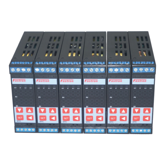
DTC1 Series
Intelligent Temperature/Humidity PID
Controller with 60 Step Program Control
User Manual V 1.0
Safety Warning
1a)Avoid touching the AC power terminals after the controller is powered
.
on
1b)Always ensure the supply power is off first before connecting any
.
wires
1c)Do not operate this instrument in places full of explosive and
combustible gases
.
2. Incorrect Connection of the Power Supply can cause permanent
damage.
3. The maximum torque of the terminals should not exceed 8KN.
4. Please do not use in the following circumstances:
● where the temperature changes dramatically
● Places where humidity is too high (~85%) and water is produced
● Where vibration or impact is high
●Where corrosive gases or dust are present
● splash of water, oil and chemicals
6. All Wiring should be kept away from highvoltage, highcurrent power
Thank you for purchasing Fastron DTC series PID
Temperature/Humidity Controller. This manual explains
how to install and operate your new PID
Before operation, please read this manual first to fully
understand the operation of this product. This controller
should be installed by a qualified Electrical Engineer,
Technician or Electrician. For specific technical support
please contact your agent or representative.
(1) Slope value offset compensation.
(2) 2 in (input) 2 out (output) : 1 to 2 isolated transmission, 2 to 1 isolated transmission
(Optional)
(3) Multiple alarm modes
(4)Transmission of PV, SV and MV: forward, reverse and difference value in 8 ways.
(5) Output soft start function.
(6) Dehumidification function.
(7) Servo Motor Control (Optional)
(8) Optional 60 Segment, Multi Sequence, Program Control
Controller.
Improved Features
Advertisement

Related Manuals for FASTRON. DTC1 Series

Summary of Contents for FASTRON. DTC1 Series
- Page 1 DTC1 Series Thank you for purchasing Fastron DTC series PID Temperature/Humidity Controller. This manual explains how to install and operate your new PID Controller. Intelligent Temperature/Humidity PID Before operation, please read this manual first to fully understand the operation of this product. This controller Controller with 60 Step Program Control should be installed by a qualified Electrical Engineer, Technician or Electrician. For specific technical support User Manual V 1.0 please contact your agent or representative. Improved Features Safety Warning (1) Slope value offset compensation. 1a)Avoid touching the AC power terminals after the controller is powered (2) 2 in (input) 2 out (output) : 1 to 2 isolated transmission, 2 to 1 isolated transmission (Optional) 1b)Always ensure the supply power is off first before connecting any (3) Multiple alarm modes wires (4)Transmission of PV, SV and MV: forward, reverse and difference value in 8 ways. 1c)Do not operate this instrument in places full of explosive and (5) Output soft start function. combustible gases . (6) Dehumidification function. 2. Incorrect Connection of the Power Supply can cause permanent (7) Servo Motor Control (Optional) damage. (8) Optional 60 Segment, Multi Sequence, Program Control 3. The maximum torque of the terminals should not exceed 8KN. 4. Please do not use in the following circumstances: ...
- Page 3 1. Sensor Type Setting 2. AL1/AL2 Alarm mode setting A. Press SET +◄ key to enter LEVEL3 A. Press SET for 5 seconds to enter LEVEL2 B. Once you reach INP Press ◄ and the SV B. Press SET several times to access AD1, then press the display will blink ◄ key and the display will start to flash. C. Press▼or▲select the input type (refer to the C. Press▼or▲select the alarm type (see alarm selection signal input selection table). Press SET to confirm table) E. At the same time, press SET +◄ to return to D. Press SET to confirm LEVEL1 E. Press SET to return to LEVEL 1 Step (3): Set alarm value AL1/AL2 Step (4): Program Control Setting and Operation (Optional) See AL1 and AL2 in alarm mode Table A. Press SET key several times to access AL1 A. At LEVEL1 master PV/SV display press SET key several selection, and then press ◄ to enable the times to reach “C01” in order to start to set the program. selection. Press ◄ and ▲ or▼ and SET to set the temperature for the B. Press▲ or▼ to SET the value, and then press frist segment. the ◄ key to move to the next digit and do Both B. Press SET to select T01. Press ◄ and ▲ or▼ and SET AL1 and AL2 can choose alarm mode from 0 to 10, to set the time for the frist segment. which can the same setting . C. Press SET several times until you reach OU01. Press ◄ C. After setting, press SET key to confirm. Pattern and ▲ or▼ and SET to set the MV high limit for the first End output can be selected as Alarm mode 11. segment. Repeat for each step to create the pattern. There is also a constant temperature and timing D. Ensure all remaining CX, TX and OUX values are set to alarm mode 19 D. Press SET to return to LEVEL1 setting and test ...
- Page 4 Example: To Set four groups as shown in the above figure In the first group, there are five stages: the first stage, the step temperature is C1, and the step time is T1.In the second segment, the end temperature is C2 and the end time is T2.In the third stage, the step temperature is C3 and the step time is T3.In the fourth section, the step temperature is C4 and the step time is T4. In paragraph 5, the step temperature is C5 and the step time is T5. The second set of seven sections: the first section, the end temperature is C7, the end time is T7 .In the second segment, the end temperature is C8 and the end time is T8. In the third section, the end temperature is C9 and the end time is T9. In the fourth segment, the end temperature is C10 and the end time is T10.In paragraph 5, the step temperature is C11 and the step time is T11. In the sixth paragraph, the step temperature is C12 and the step time is T12.In the seventh section, the end temperature is C13 and the end time is T13. The third set of three sections: the first section, the end temperature is C15, the end time is T15. In the second segment, the end temperature is C16 and the end time is T16. In the third section, the end temperature is C17 and the end time is T17. The fourth set of five segments: the first segment, the end temperature is C19, the end time is T19.In the second segment, the end temperature is C20 and the end time is T20.In the third section, the step temperature is C21 Step (5): Autotuning(AT) Function A. Once installed in the field, carry out selftuning to allow the controller to determine the optimum AT parameters. B. AT calculation will choose the optimum PID Parameters based on the controllers auto tuning algorithm. C. The maximum value of the process curve should be about 80% of the range of instrument detection. D. Before the program is not started (fixed value control STA=0), it is better to carry out AT around the maximum value of the process curve (SV=0.3). E. In LEVEL1 process, press SET key several times to reach AT option, Step (6) Manually modifying PID parameters. (Optional Fine Tuning) Use the below duie to change the P, I, D values for fine tuning of manual tuning (LEVEL 2)
-
Page 5: Dehumidification Function
Soft Start Function Output Soft Start To enable simple soft start feature set the SV as follows; Set SV value > In level3 press SET key to reach DLY, SET the output soft start value in seconds (I.e. if DLY is set to 10, then the soft start time will be 10 seconds). Exit the menu by pressing set until you return to the main screen. Now the soft start function is activated when the control is set to begin heating. Rate of Change/Slope Temperature Limit When your system needs a soft start (SV preset slope heating), please operate in the following order: SET SV value→ at LEVEL1, press SET key to find RAP to SET slope temperature value, and →then press SET key to find RTM to SET slope time in minutes(for example, SET slope to 10 / min, RAP to 10.0, RTM to 001.0) →after setting, SV value will be SET immediately from the current PV value to 10 / min, until reaching the SET SV value. Slope heating process PRO The output percentage of normal temperature lights flashing control process is automatically controlled by PID Dehumidification Function For systems which require dehumidification function. In Level 1 Menu, press SET button several times to reach SRT to preset dehumidification PV value, (Most common range is 1040 Deg C) press SET key again and reach LMO to preset dehumidification work output percentage, generally 2.0 to 5.0%. For example for SRT = 40, and LMO = 2%, the Controller will output at 2% when the system temperature drops below 40 Deg C. This feature can help avoid heater burnout. The above curve shows two points, the Dip in the heating curve is caused by the dehumidification setting. The second point is the normal output of the PID Controller. - Page 6 Jumper Settings for TC Jumper Settings for RTD Note : future version V1.2 will have full multirange input type without Jumper selection ...