Advertisement
Quick Links
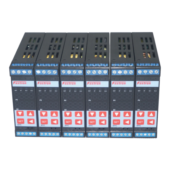
DTC1 Series
Intelligent Temperature/Humidity PID
Controller with 60 Step Program Control
User Manual V 1.0
Safety Warning
1a)Avoid touching the AC power terminals after the controller is powered
.
on
1b)Always ensure the supply power is off first before connecting any
.
wires
1c)Do not operate this instrument in places full of explosive and
combustible gases
.
2. Incorrect Connection of the Power Supply can cause permanent
damage.
3. The maximum torque of the terminals should not exceed 8KN.
4. Please do not use in the following circumstances:
● where the temperature changes dramatically
● Places where humidity is too high (~85%) and water is produced
● Where vibration or impact is high
●Where corrosive gases or dust are present
● splash of water, oil and chemicals
6. All Wiring should be kept away from highvoltage, highcurrent power
For application notes and examples please visit
https://fastron.com.au/blogs/pidtemperaturecontrollers
Thank you for purchasing Fastron DTC series PID
Temperature/Humidity Controller. This manual explains
how to install and operate your new PID
Before operation, please read this manual first to fully
understand the operation of this product. This controller
should be installed by a qualified Electrical Engineer,
Technician or Electrician. For specific technical support
please contact your agent or representative.
(1) Slope value offset compensation.
(2) 2 in (input) 2 out (output) : 1 to 2 isolated transmission, 2 to 1 isolated transmission
(Optional)
(3) Multiple alarm modes
(4)Transmission of PV, SV and MV: forward, reverse and difference value in 8 ways.
(5) Output soft start function.
(6) Dehumidification function.
(7) Servo Motor Control (Optional)
(8) Optional 60 Segment, Multi Sequence, Program Control
Controller.
Improved Features
Advertisement

Related Manuals for FASTRON. DTC1 Series

Summary of Contents for FASTRON. DTC1 Series
- Page 1 Controller with 60 Step Program Control should be installed by a qualified Electrical Engineer, Technician or Electrician. For specific technical support User Manual V 1.0 please contact your agent or representative. Improved Features Safety Warning (1) Slope value offset compensation. 1a)Avoid touching the AC power terminals after the controller is powered (2) 2 in (input) 2 out (output) : 1 to 2 isolated transmission, 2 to 1 isolated transmission (Optional) 1b)Always ensure the supply power is off first before connecting any (3) Multiple alarm modes wires (4)Transmission of PV, SV and MV: forward, reverse and difference value in 8 ways. 1c)Do not operate this instrument in places full of explosive and (5) Output soft start function. combustible gases . (6) Dehumidification function. 2. Incorrect Connection of the Power Supply can cause permanent (7) Servo Motor Control (Optional) damage. (8) Optional 60 Segment, Multi Sequence, Program Control 3. The maximum torque of the terminals should not exceed 8KN. 4. Please do not use in the following circumstances: ● where the temperature changes dramatically ● Places where humidity is too high (~85%) and water is produced ● Where vibration or impact is high ●Where corrosive gases or dust are present ● splash of water, oil and chemicals 6. All Wiring should be kept away from highvoltage, highcurrent power For application notes and examples please visit https://fastron.com.au/blogs/pidtemperaturecontrollers...
-
Page 3: Soft Start Function
1. Sensor Type Setting 2. AL1/AL2 Alarm mode setting A. Press SET +◄ key to enter LEVEL3 A. Press SET for 5 seconds to enter LEVEL2 B. Once you reach INP Press ◄ and the SV B. Press SET several times to access AD1, then press the display will blink ◄ key and the display will start to flash. C. Press▼or▲select the input type (refer to the C. Press▼or▲select the alarm type (see alarm selection signal input selection table). Press SET to confirm table) E. At the same time, press SET +◄ to return to D. Press SET to confirm LEVEL1 E. Press SET to return to LEVEL 1 Step (3): Set alarm value AL1/AL2 Step (5): Autotuning(AT) Function See AL1 and AL2 in alarm mode Table A. Once installed in the field, carry out selftuning to allow A. Press SET key several times to access AL1 the controller to determine the optimum AT parameters. selection, and then press ◄ to enable the B. AT calculation will choose the optimum PID Parameters selection. based on the controllers auto tuning algorithm. B. Press▲ or▼ to SET the value, and then press C. The maximum value of the process curve should be the ◄ key to move to the next digit and do Both about 80% of the range of instrument detection. AL1 and AL2 can choose alarm mode from 0 to 10, D. Before the program is not started (fixed value control which can the same setting . STA=0), it is better to carry out AT around the maximum C. After setting, press SET key to confirm. Pattern value of the process curve (SV=0.3). E. In LEVEL1 End output can be selected as Alarm mode 11. process, press SET key several times to reach AT option, There is also a constant temperature and timing then press and key to put "1" to start AT calculation. alarm mode 19 F. This machine is used as a fixed value control when STA ... -
Page 4: Troubleshooting
Troubleshooting DTC1 C5 Communications Manual RS485 MODBUS RTU communication 1.Scope of selection: Fastron Electronics DTC Series fitted with RS485 protocol Modbus RTU “C5” Option Baud rate :4800, 9600, 19200, 38400, 76800, 2.Work realization: data exchange between instrument and host computer 153600 bps (instrument can only be used as slave to receive interrogation and reply) Start position: 1 3.Serial transmission mode: RTU Data bit: 8 4.Transmission interface: RS485 Check bit: E(even), N(none) Stop bits: 1, 2 5.Communication medium: shielded twisted pair Frame check method: (CRC16) 6.Communication stack number: 1~255. The upper limit of the number of Message format: (N=2) connecting meters is related to the load capacity of the host, typically over 15 Communication Application Notes or 31 meters require signal Isolator/amplifier. 1. Read AM and AM1(cold control manual) menus,0 represents 7.Function code implementation: read hold register (03), write single register manual state,1 represents automatic state. (06), write multiple registers (10) 2. RAP is the program control menu, read, return 0X0000 8.Data length: represents the program control close, return 0X0001 represents 8a) When writing data to the controller, a maximum of 16 consecutive the program control start: write 0X0000 to close the program instructions (32 bytes) can be written at one time. control, write 0X0001 to start the program control, write 0X0002 8b) When reading the menu data inside the machine, the nonprogrammed to stop the program control, write 0X0002 to end the ... - Page 5 DTC1 Series C5 Communication Manual...
Need help?
Do you have a question about the DTC1 Series and is the answer not in the manual?
Questions and answers