Table of Contents
Advertisement
Quick Links
Advertisement
Table of Contents

Summary of Contents for V&T TS-I Series
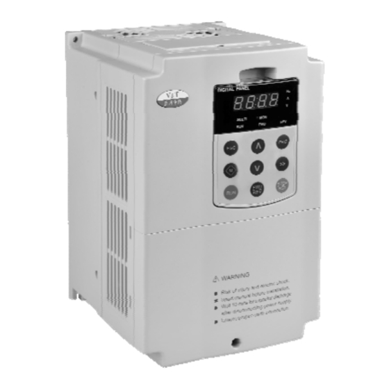
- Page 1 User Manual TS−I series servo drive is introdution &...
- Page 3 Foreword TS−I series synchronous servo driver is a high performance and highly reliable servo driver with high responding speed for electrolytic mixing system of the injection molding machine. The product is based on a flexible digital control module that uses high performance DSP, which realizes high performance vector control, precision position and speed control, non-linear weak magnetic high speed control and position calibration space vector low speed control for each kind of control algorithm and software for...
- Page 4 High Reliability Design Meeting the Relevant International Product Standards General requirements–Rating specifications for low voltage adjustable IEC61800−2 frequency a.c. power drive systems IEC61800−3 EMC product standard including specific test methods IEC61000−6 Electromagnetic compatibility(EMC)–Part6:Generic standards IEC61800−5−1 Safety requirements –Electrical, thermal and energy UL508C UL Standard for Safety for Power Conversion Equipment Integrated Design...
- Page 5 reliability of the system. Independent power supply for control: The driver provides an independent DC input interface. External UPS power supply can be connected to the driver through an option card. It is applicable to the applications of oilfield, chemical industry and printing and dyeing industry.
- Page 6 Customized Functions Multiple Function Code Display Modes bASE: Basic menu mode, displays all the function codes. FASt : Fast menu mode,display the common parameters to be used in the commissioning,is especially suitable for the naive users. ndFt: Non-factory setting menu mode, it only displays the function codes different from the leave-factory values to facilitate the inquiry and commissioning.
- Page 7 Safety Precautions Description of safety marks: Danger: The misuse may cause fire, severe injury, even death. Note: The misuse may cause medium or minor injury and equipment damage. Danger Danger This series synchronous servo driver is used to control the 3-phase (single phase) permanent magnetic synchronous motor (PMSM), cannot be used for single-phase motor or other applications.
- Page 8 Wiring Danger Danger The wiring must be conducted by qualified electricians. Otherwise, electric shock may happen or driver damage. Before wiring, confirm that the power supply is disconnected. Otherwise, electric shock may happen or fire. The PE terminal must be reliably grounded, and should use the third grounding method for grounding the PMSM motor at equal voltage potential, otherwise, the driver enclosure may become live.
- Page 9 Operation Danger Danger Power supply can only be connected after the wiring is completed and the cover is installed. It is forbidden to remove the cover in live condition; otherwise, electric shock may happen. When auto failure reset function or restart function is enabled, isolation measures shall be taken for the mechanical equipment, otherwise, personal injury may be caused.
- Page 10 Note Note The circuit boards have large scale CMOS IC. Please do not touch the board to avoid the circuit board damage caused by ESD. Others Danger Danger It is forbidden to modify the driver unauthorizedly; otherwise, human injury may be caused.
-
Page 11: Table Of Contents
目 录 Chapter 1 TS−I series servo drive is introdution ............... 1 1.1 Product Model Description ..................... 1 1.2 Product Nameplate Description..................1 1.3 A series of models and technical parameters of product ..........2 1.4 Product Component Name ..................... 3 1.5 Product Outline, Mounting Dimension, and Weight ............ - Page 12 目 录 Chapter 4 Parameters and debugging of servo drive............39 4.1 List of Basic Menu Function Codes ................39 4.2 X multifunctional terminal definition table ..............52 4.3 Definition of multi function relay and Y terminal output..........52 4.4 Definition of multi function analog value A0 output ............53 Chapter 5 Alarm and diagnosis of servo drive..............
-
Page 13: Chapter 1 Ts−I Series Servo Drive Is Introdution
TS−I Special servo drive for hybrid electro-hydraulic system of injection molding machine User Manual Chapter 1 TS−I series servo drive is introdution 1.1 Product Model Description The digits and letters in the driver model field on the nameplate indicate such information as the driver series, power supply class, power class and software/hardware versions. -
Page 14: A Series Of Models And Technical Parameters Of Product
TS−I Special servo drive for hybrid electro-hydraulic system of injection molding machine User Manual 1.3 A series of models and technical parameters of product Three-phase 400V Constant torque/heavy-duty application servo driver The input voltage The power supply The input Output Overload capacity model capacity (KVA)... -
Page 15: Product Component Name
TS−I Special servo drive for hybrid electro-hydraulic system of injection molding machine User Manual 1.4 Product Component Name Mounting hole Mounting hole Mounting hole Dust guard Dust guard Cooling fan Cooling fan Heatsink Upper cover Enclosure Operation panel Operation panel Nameplate Nameplate Nameplate... - Page 16 TS−I Special servo drive for hybrid electro-hydraulic system of injection molding machine User Manual Product outline, mounting dimension, and weight Outline and mounting dimension (mm) Approxim servo driver Mounting ate weight model hole (kg) diameter TS−I−4T009A 60.5 TS−I−4T013A TS−I−4T017A TS−I−4T024A TS−I−4T030A TS−I−4T039A Voltage...
-
Page 17: Operation Panel Outline And Mounting Dimension
TS−I Special servo drive for hybrid electro-hydraulic system of injection molding machine User Manual 1.6 Operation Panel Outline and Mounting Dimension Button type operation panel(V6−DP02) Rear view of operation panel Figure 1-3 Operation panel outline and mounting dimension V6−DP05 is the mounting pallet when the operation panel is to install on the electric control cabinet. The outline and dimension are as follows: Pallet(V6−DP05)... -
Page 18: Models Of Braking Resistor
TS−I Special servo drive for hybrid electro-hydraulic system of injection molding machine User Manual 1.7 Models of Braking Resistor Braking resistor unit servo driver model Braking unit Braking Braking resistor Braking resistor Qty. power torque% TS−I−4T009A 390W 150Ω TS−I−4T013A 500W 100Ω... -
Page 19: Chapter 2 Installation And Connection Of Servo Driver
TS−I Special servo drive for hybrid electro-hydraulic system of injection molding machine User Manual Chapter 2 Installation and connection of servo driver 2.1 Environment for Product Installation Do not install the driver in the sites with oil mist, metal powder and dust. Do not install the driver in the sites with hazardous gas and liquid, and corrosive, combustible and explosive gas. -
Page 20: Removal And Mounting Of Operation Panel And Cover
TS−I Special servo drive for hybrid electro-hydraulic system of injection molding machine User Manual Above 200mm Air circulation position Air circulation position Above 200mm Above 30mm Above 30mm Figure 2−2 Mounting direction and space for V5−H−4T11G/15L and above power class 2.3 Removal and Mounting of Operation Panel and Cover 2.3.1 Removal and Mounting of Operation Panel Removal of operation panel... - Page 21 TS−I Special servo drive for hybrid electro-hydraulic system of injection molding machine User Manual in direction 1 and at the same time lift the cover in direction 2, as shown in Figure 2−5. Removal of upper cover As shown in Figure 2−6, press the left and right sides of the cover forcefully in direction 1, and at the same time lift the cover in direction 2.
- Page 22 TS−I Special servo drive for hybrid electro-hydraulic system of injection molding machine User Manual Figure 2−9, and then take out the cover in direction 2. Mounting of cover After connecting the cables of main circuit terminals and control circuit terminals, cramp the cover in direction 1 as shown in Figure 2−10, press down the cover in direction 2 and then tighten the cover screws.
-
Page 23: Connection Of The Driver And Peripheral Devices
TS−I Special servo drive for hybrid electro-hydraulic system of injection molding machine User Manual 2.4 Connection of the driver and Peripheral Devices Power supply Circui Contactor Input AC reactor Computer Input noise filter injection Driver Grounding Pressure sensor The encoder plug Groundi Braking resistor Motor... -
Page 24: Description Of Peripheral Devices For Main Circuit
TS−I Special servo drive for hybrid electro-hydraulic system of injection molding machine User Manual 2.5 Description of Peripheral Devices for Main Circuit The circuit breaker capacity shall be 1.5 ~ 2 times of the driver rated current. Circuit breaker The time features of the circuit breaker shall fully consider the time features of the driver overload protection. -
Page 25: Models Of Main Circuit Peripheral Devices
TS−I Special servo drive for hybrid electro-hydraulic system of injection molding machine User Manual 2.6 Models of Main Circuit Peripheral Devices ⊕ ⊕ PE terminal R/L1、S/L2、T/L3、 1、 2/B1、 Ө B2、 、U/T1、V/T2、W/T3 Circuit Contacto Wire Wire Drive model Breaker Tightening Tightening Termina specific Termina... -
Page 26: Functions Of Main Circuit Terminal
TS−I Special servo drive for hybrid electro-hydraulic system of injection molding machine User Manual 2.7 Functions of Main Circuit Terminal 2.7.1 TS−I−4T030A And the following Terminal symbol Terminal name and function description R/L1、S/L2、T/L3 Three-phase AC input terminal ⊕ ⊕ 1、 2/B1 DC reactor connecting terminal, short circuited with copper bus upon delivery ⊕... -
Page 27: Attention For Main Circuit Wiring
TS−I Special servo drive for hybrid electro-hydraulic system of injection molding machine User Manual 2.7.3 TS−I−4T176A~TS−I−4T304AThe built-in braking unit options The drive of TS−I−4T176~TS−I−4T304 adopt the top cable-inlet bottom cable-outlet wiring mode. Sketch Map Terminal symbol Terminal name and function description R/L1、S/L2、T/L3 Three-phase AC input terminal ⊕... - Page 28 TS−I Special servo drive for hybrid electro-hydraulic system of injection molding machine User Manual should be installed if the motor cable is longer than 100m. Refer to the following table for the carrier frequency setting. Length of cable between the Less than 50m Less than 100 m More than 100m...
- Page 29 TS−I Special servo drive for hybrid electro-hydraulic system of injection molding machine User Manual The input power wire and output motor wire shall be kept away from each other as long as possible. The equipment and signal cables vulnerable to EMI shall be kept far away from the driver. Key signal cables shall adopt shielded cable.
-
Page 30: Connection Of Rotating Pg And Temperature Sensor Cable Of The Motor
TS−I Special servo drive for hybrid electro-hydraulic system of injection molding machine User Manual 2.9 Connection of rotating PG and temperature sensor cable of the motor 2.9.1 Appearance of connection terminal 2.9.2 Defintion of pins and illustration drawing Name Description of function Definition of pins COS- COS−... -
Page 31: The Main Circuit And The Control Terminal Of A Circuit Wiring Diagram
TS−I Special servo drive for hybrid electro-hydraulic system of injection molding machine User Manual 2.10 The main circuit and the control terminal of a circuit wiring diagram Chapter 2 Installation and connection of servo driver... -
Page 32: The Control Circuit Terminal Function
TS−I Special servo drive for hybrid electro-hydraulic system of injection molding machine User Manual 2.11 The control circuit terminal function Terminal Type Terminal function description Technical specification symbol Rate: 4800/9600/19200/38400/57600bps Positive end of RS485 differential signal 485+ Up to 32 sets of equipment can be paralleled*. Relay shall be used if the number exceeds 32. - Page 33 TS−I Special servo drive for hybrid electro-hydraulic system of injection molding machine User Manual RA−RB: NC Relay RA/RB/RC Relay output RA−RC: NO output 1 Contact capacity: 250VAC/1A,30VDC/1A RA−RB: NC Relay RA1/RB1 Relay output output 2 Contact capacity: 250VAC/1A,30VDC/1A Note: ﹡ If the user connects adjustable potentiometer between +10V and GND, the resistance of the potentiometer shall be no less than 5kΩ, 1.
- Page 34 TS−I Special servo drive for hybrid electro-hydraulic system of injection molding machine User Manual Note: The short circuit bar between terminal +24V and terminal PLC must be removed and short circuit bar shall be connected between PLC and COM terminals. When the external power supply is used, the external controller adopts NPN sink current wiring mode.
-
Page 35: Schematic Diagram Of Control Board
TS−I Special servo drive for hybrid electro-hydraulic system of injection molding machine User Manual 2.12 Schematic Diagram of Control Board 2.13 Descriptions of Control Circuit Terminals Tightening Termina Wire specification Terminal number torque Wire type l screw (N·m) +10V、+13V、AI1、AI2、AI3、CANH、 Shielded twisted 0.5~0.6 0.75 pair cable... -
Page 36: Description Of Jumper Function
TS−I Special servo drive for hybrid electro-hydraulic system of injection molding machine User Manual 2.14 Description of Jumper Function Jumper control panel select switch: Name Function Leave-factory setting RS485 terminal resistor selection: ON: there is 100Ω terminal resistor, There is no terminal resistor OFF: there is no terminal resistor AI2 selection mode: I is the current input (0~20mA), V is the voltage 0~10V voltage input... -
Page 37: Cautions For Installing Servo Motor And Pressure Sensor
TS−I Special servo drive for hybrid electro-hydraulic system of injection molding machine User Manual 2.15 Cautions for installing servo motor and pressure sensor Installation method of servo motor Installation method of pressure sensor Chapter 2 Installation and connection of servo driver... -
Page 38: Chapter 3 Digital Actuator Button, Display And Motor Learning
TS−I Special servo drive for hybrid electro-hydraulic system of injection molding machine User Manual Chapter 3 Digital actuator button, display and motor learning 3.1 Introduction to Operation Panel Figure 3−1 Display unit of operation panel 3.2 Descriptions of Indicators Symbol of Indicator Name Meanings Color... -
Page 39: Descriptions Of Indicators
TS−I Special servo drive for hybrid electro-hydraulic system of injection molding machine User Manual 3.3 Descriptions of Indicators Symbol Name Function Key-type 1、 Enter each level of menu Programmin 2、 Validate data change g key 3、 Check function code in sequence 4、... -
Page 40: Menu Style
TS−I Special servo drive for hybrid electro-hydraulic system of injection molding machine User Manual 3.4 Menu Style The menu style is 2-level menu. 3.4.1 Format of First Level Menu Function code area Group number Separation sign Index in group Figure 3−2 Format of first level menu Dividing the first level menu Password action area Function code area... - Page 41 TS−I Special servo drive for hybrid electro-hydraulic system of injection molding machine User Manual Structure of first level menu Menu structure 3.4.2 Format of Second Level Menu Data bit 2 Decimal point Data bit 3 Data bit 4 Data bit 1 Format of display/set for second level menu Display/set decimal:...
- Page 42 TS−I Special servo drive for hybrid electro-hydraulic system of injection molding machine User Manual 3.4.3 Menu Mode Menu mode Operation panel setting Menu mode name Visible function code range display (P0.02) See 5.1 for the table of basic menu function Basic menu bASE code parameter...
- Page 43 TS−I Special servo drive for hybrid electro-hydraulic system of injection molding machine User Manual 3.4.4 Common Characters Displayed by LED Except the function codes in first and second level menus, the operation panel will also display the following characters as shown in the following table: Prompt Prompt Meaning...
-
Page 44: Password Operation
TS−I Special servo drive for hybrid electro-hydraulic system of injection molding machine User Manual 3.4.5 Identify Symbols Displayed Via LED The relationship between characters displayed by LED and characters/numbers are as follows: Meanings of Meanings of Meanings of Meanings of LED display LED display LED display... -
Page 45: Lock/Unlock Keys
TS−I Special servo drive for hybrid electro-hydraulic system of injection molding machine User Manual “Loc2”(P2.00=2) or “Loc3”(P2.00=3) is displayed. 2. Do not press any key for continuous 5 minutes. 3. Restart the drive 3.6 Lock/Unlock Keys Lock Keys Set the function of locking keys Select the P2.00 key locking functions: 0: Do not lock the keys on the operation panel and all the keys can be used;... -
Page 46: Operation Example
TS−I Special servo drive for hybrid electro-hydraulic system of injection molding machine User Manual In the display status of stopping and running parameters, press ∧ and ∨ to Password modification status enter. Information prompt status See 4.4.5 for identifying the LED display characters. 3.7.2 Display Status and Operation Process >>... -
Page 47: Running For The First Time
TS−I Special servo drive for hybrid electro-hydraulic system of injection molding machine User Manual For example, setting P0.01=3: Restore all the parameters in P area to factory settings except the motor parameters (F9 group). 3.8.2 Setting Frequency For example, setting P0.05=25.00Hz. 3.8.3 Setting Password For example, set user password P0.00 0003. - Page 48 TS−I Special servo drive for hybrid electro-hydraulic system of injection molding machine User Manual Start Before power up, confirm the wiring is correct Set the P0.04=0 setting Set the parameters of the motor parameters of motor P9.02~P9.07 Set the P9.23=1 P9.24=1 press the RUN button to Motor tuning display the -At- after stopping...
-
Page 49: Commissioning Instructions For Servo Pump
TS−I Special servo drive for hybrid electro-hydraulic system of injection molding machine User Manual 3.10 Commissioning Instructions for Servo Pump 3.10.1 Motor Tuning Set motor parameters correctly according to the motor nameplate Set parameter P0.04=0 “Speed setting mode” to “Set via panel digitally (P0.05)”, then set P9.02=rated rotating speed, P9.03=rated power, P9.04=rated current, P9.05=rated voltage, P9.06=rated torque, P9.07=torque current coefficient Kt according to the nameplate of the motor. - Page 50 TS−I Special servo drive for hybrid electro-hydraulic system of injection molding machine User Manual If the pressure flow has zero-drift voltage, you can neutralize this voltage by setting P6.11(Min pressure) and P6.13 (Min flow). 3.10.4 PID for regulating oil pressure Start the driver, and the injection molding machine acts (the oil tank acts to its limit), set the pressure signal output from small value to big value to test the stability of the pressure.
-
Page 51: Chapter 4 Parameters And Debugging Of Servo Drive
TS−I Special servo drive for hybrid electro-hydraulic system of injection molding machine User Manual Chapter 4 Parameters and debugging of servo drive Meanings of Each Item in Function Code Parameter Table Item M e a n i n g s Function code number The number of function code, such as P0.00 Function code name... - Page 52 TS−I Special servo drive for hybrid electro-hydraulic system of injection molding machine User Manual Function Factory Prop User code Function code name Setting range Unit Function code selection setting erty setting number 3: Issue via multi pump CAN; 4: Issue via RS485 5: Issue via CAN+485 P0.05 Digital speed preset speed...
- Page 53 TS−I Special servo drive for hybrid electro-hydraulic system of injection molding machine User Manual Function Factory Prop User code Function code name Setting range Unit Function code selection setting erty setting number Group P2 Key and Display Parameters 0: No locking; 1: Locking all keys;...
- Page 54 TS−I Special servo drive for hybrid electro-hydraulic system of injection molding machine User Manual Function Factory Prop User code Function code name Setting range Unit Function code selection setting erty setting number Stopping proportion display P2.06 0~F ○ benckmark Stopping proportion display P2.07 0~1000.0% ○...
- Page 55 TS−I Special servo drive for hybrid electro-hydraulic system of injection molding machine User Manual Function Factory Prop User code Function code name Setting range Unit Function code selection setting erty setting number P4.11 ASR output filtering time 0~500.0 ○ Group P5 X multifunctional terminal parameters X1 terminal input function P5.00 0~99...
- Page 56 TS−I Special servo drive for hybrid electro-hydraulic system of injection molding machine User Manual Function Factory Prop User code Function code name Setting range Unit Function code selection setting erty setting number P6.11 AI1 The minimum value 0.06 0~2.00 ○ P6.12 AI2 The minimum value 0.06...
- Page 57 TS−I Special servo drive for hybrid electro-hydraulic system of injection molding machine User Manual Function Factory Prop User code Function code name Setting range Unit Function code selection setting erty setting number Units bit: merging type 0: Single pump 1: Multi pump merging 2: Multi pump merging &...
- Page 58 TS−I Special servo drive for hybrid electro-hydraulic system of injection molding machine User Manual Function Factory Prop User code Function code name Setting range Unit Function code selection setting erty setting number P9.01 Number of motor poles 2~128 × P9.02 Rated rotating velocity of motor 2000 0~9999...
- Page 59 TS−I Special servo drive for hybrid electro-hydraulic system of injection molding machine User Manual Function Factory Prop User code Function code name Setting range Unit Function code selection setting erty setting number 0: No masking, stop upon fault 1: No masking, do not stop upon fault 2: Masked, do not alarm and do not stop upon fault...
- Page 60 TS−I Special servo drive for hybrid electro-hydraulic system of injection molding machine User Manual Function Factory Prop User code Function code name Setting range Unit Function code selection setting erty setting number : No function; 1: Parameter uploading; 2: Parameter downloading (without motor parameters);...
- Page 61 TS−I Special servo drive for hybrid electro-hydraulic system of injection molding machine User Manual Function Factory Prop User code Function code name Setting range Unit Function code selection setting erty setting number Max current for weak magnetic 0.0~ Pd.09 × control PA9.04*90% Proportional coefficient for weak...
- Page 62 TS−I Special servo drive for hybrid electro-hydraulic system of injection molding machine User Manual Function Factory Prop User code Function code name Setting range Unit Function code selection setting erty setting number AI1 percentage after curvilinear d2.02 0~100.0 transformation AI2 percentage after curvilinear d2.03 0~100.0 transformation...
- Page 63 TS−I Special servo drive for hybrid electro-hydraulic system of injection molding machine User Manual Function Factory Prop User code Function code name Setting range Unit Function code selection setting erty setting number Adjustment coefficient for H0.14 21.4 0.0~160.0 ○ 30kgf/cm2 reference pressure Adjustment coefficient for H0.15 14.3 0.0~160.0...
-
Page 64: Multifunctional Terminal Definition Table
TS−I Special servo drive for hybrid electro-hydraulic system of injection molding machine User Manual 4.2 X multifunctional terminal definition table Definition table for multi function terminal X Definition of function Communication enabled Servo enable Fault reset Using the second group pressure PI External fault input Using the third group pressure PI Motor temperature switch PTC/KTY input... -
Page 65: Definition Of Multi Function Analog Value A0 Output
TS−I Special servo drive for hybrid electro-hydraulic system of injection molding machine User Manual 4.4 Definition of multi function analog value A0 output Definition of multi function analog value A0 output Function design Output signal selection AO output range definition P0.13 max speed P0.13 corresponds to 10V/20mA Speed setting... -
Page 66: Chapter 5 Alarm And Diagnosis Of Servo Drive
TS−I Special servo drive for hybrid electro-hydraulic system of injection molding machine User Manual Chapter 5 Alarm and diagnosis of servo drive 5.1 Faults and Solutions TS−I serial driver is equipped with complete protection functions to provide efficient protection while utilizing its performance sufficiently. - Page 67 TS−I Special servo drive for hybrid electro-hydraulic system of injection molding machine User Manual Failure Failure Failure description Potential causes Solutions code Enable auto-tuning function during Perform auto-tuning after the motor spining motor stops to rotate Check whether motor wirings are well connected Auto-tuning overtime E.AUt...
- Page 68 TS−I Special servo drive for hybrid electro-hydraulic system of injection molding machine User Manual Failure Failure Failure description Potential causes Solutions code Check the external failure External failure terminal enable terminal status E.oUt Peripheral protection Stall over voltage or over current and Check whether the external load the time lasts for more than one is normal...
- Page 69 TS−I Special servo drive for hybrid electro-hydraulic system of injection molding machine User Manual Failure Failure Failure description Potential causes Solutions code E.EEP EEPROM failure EEPROM reading and writing failure Seek for technical support Loose connection of connectors inside Ask professional technicians to the drive maintain E.dL3...
- Page 70 TS−I Special servo drive for hybrid electro-hydraulic system of injection molding machine User Manual Failure Failure Failure description Potential causes Solutions code with the requirements Check whether the communication timeout is set The communication of RS485 terminal properly and confirm the is time-out communication cycle of the application program...
-
Page 71: Troubleshooting Procedures
TS−I Special servo drive for hybrid electro-hydraulic system of injection molding machine User Manual 5.2 Troubleshooting Procedures Chapter 5 Alarm and diagnosis of servo drive... -
Page 72: Chapter 6 Debugging, Selection And Function Application
TS−I Special servo drive for hybrid electro-hydraulic system of injection molding machine User Manual Chapter 6 Debugging, selection and function application 6.1 Answer the questions in debugging process I. Why did the keyboard will have “8.8.8.8” display or have no display sometimes? A: (1) Check if the connectors are properly connected when the operation panel is directly connected to the drive control board;... - Page 73 TS−I Special servo drive for hybrid electro-hydraulic system of injection molding machine User Manual V. Why does the motor not rotate? A: 5.1 Why the motor does not run when the pressure and flow commands are issued? (1) Check if the P0.06 operation instruction functions properly, if P0.06=1, then the terminal is working, please check the X terminal’s multiple function selection and if the said terminal is closed properly.
- Page 74 TS−I Special servo drive for hybrid electro-hydraulic system of injection molding machine User Manual VII. Unstable when the system pressure is high A:(1)PID regulation fails; A:(2)Output torque of driver reaches the max output torque; A:(3)Motor torque is small, severe overload; A:(4)Driver current reaches the max current output;...
-
Page 75: Method Of Selecting The Main Components Of The Injection Molding Machine Electrolytic Mixing System
TS−I Special servo drive for hybrid electro-hydraulic system of injection molding machine User Manual 6.2 Method of selecting the main components of the injection molding machine electrolytic mixing system According to the manufacturer’s parameters, the available information: System flow is Q (L/min); System pressure is Pe (kgf/cm2);... - Page 76 TS−I Special servo drive for hybrid electro-hydraulic system of injection molding machine User Manual 6.2.3 Selection of servo driver After selecting the servo pump and servo motor, you can get the Kt factor from the manufacturer of the servo motor and then calculate the max operating current based on this factor: I=Tmax/Kt(A)...
-
Page 77: Multi Pump Control Method
TS−I Special servo drive for hybrid electro-hydraulic system of injection molding machine User Manual 6.3 Multi pump control method Generally there are two basic methods for multi pump control: Multi pump merged flow and multi pump split/merging flow, and many more methods and solutions can be obtained based on these two methods. Multi pump merged flow One injection molding machine is consisted of many servo electrolytic mixing systems, one system is the master and the others are slave and work in parallel, and they act, run and stop synchronously, and their working mode is identical with one servo pump system>... - Page 78 TS−I Special servo drive for hybrid electro-hydraulic system of injection molding machine User Manual 2. Multi pump split / merged structure The wiring method of main oil circuit and the second oil circuit system is identical with that of the single unit.
- Page 79 English version: TS−20141230−I−1.0 (BOM: 37110041) printed for the first time This document is subject to change without notice. All rights reserved. Any unauthorized reproduction or copy is forbidden.
Need help?
Do you have a question about the TS-I Series and is the answer not in the manual?
Questions and answers