Table of Contents
Advertisement
Quick Links
All manuals and user guides at all-guides.com
Page 1 of 28
INSTRUCTION MANUAL
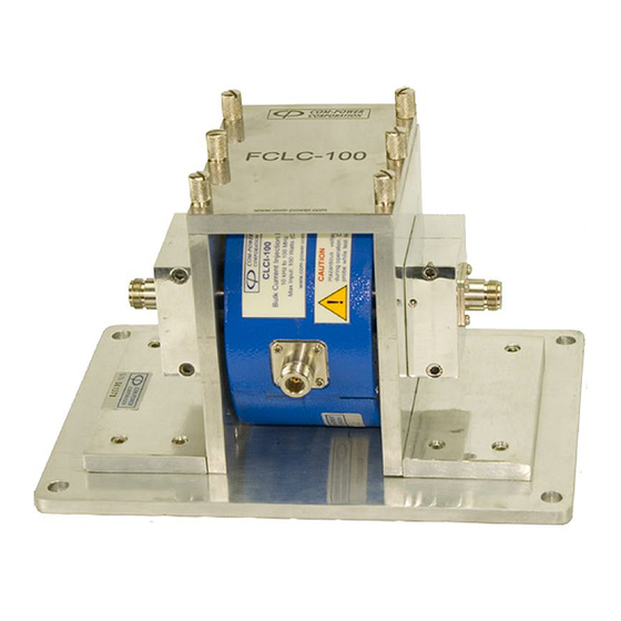
CLCI-100 BULK CURRENT INJECTION PROBE
with FCLC-100 CALIBRATION FIXTURE
INSTRUCTION MANUAL
For
BULK CURRENT
INJECTION PROBE
CLCI-100
Model:
and
CALIBRATION FIXTURE
FCLC-100
Model:
(optional)
1 9 1 2 1 E l T o r o R d ● S i l v e r a d o , C a l i f o r n i a 9 2 6 7 6 ● ( 9 4 9 ) 4 5 9 - 9 6 0 0 ● c o m - p o w e r . c o m
REV051917
Advertisement
Table of Contents

Related Manuals for Com-Power CLCI-100

Summary of Contents for Com-Power CLCI-100
- Page 1 All manuals and user guides at all-guides.com Page 1 of 28 INSTRUCTION MANUAL CLCI-100 BULK CURRENT INJECTION PROBE with FCLC-100 CALIBRATION FIXTURE INSTRUCTION MANUAL BULK CURRENT INJECTION PROBE CLCI-100 Model: CALIBRATION FIXTURE FCLC-100 Model: (optional) 1 9 1 2 1 E l T o r o R d ● S i l v e r a d o , C a l i f o r n i a 9 2 6 7 6 ● ( 9 4 9 ) 4 5 9 - 9 6 0 0 ● c o m - p o w e r . c o m...
-
Page 2: Table Of Contents
Product Warning/Caution Statements..................7 3.3.3 General Safety Instructions......................7 3.4 Product Features ......................8 3.4.1 Description of CLCI-100 Bulk Current Injection Probe Features ..........8 3.4.2 Description of FCLC-100 Calibration Fixture Features............. 9 3.5 Product Specifications ....................10 3.5.1 Specifications for CLCI-100 Bulk Current Injection Probe............. 10 3.5.2... - Page 3 CLCI-100 Bulk Current Injection Probe Features FIGURE 2 - FCLC-100 Calibration Fixture Features FIGURE 3 - Dimensional Diagram for CLCI-100 Bulk Current Injection Probe FIGURE 4 - Dimensional Diagram for FCLC-100 Calibration Fixture FIGURE 5 - Installation of CLCI-100 Probe into FCLC Calibration Fixture FIGURE 6 - Setup for Insertion/Coupling Loss in a 50Ω...
-
Page 4: Introduction
Information contained in this manual is the property of Com-Power Corporation. It is issued with the understanding that the material may not be reproduced or copied without the express written permission of Com-Power. -
Page 5: Products Available From Com-Power
All manuals and user guides at all-guides.com Page 5 of 28 INSTRUCTION MANUAL CLCI-100 BULK CURRENT INJECTION PROBE with FCLC-100 CALIBRATION FIXTURE 2.0 Products Available from Com-Power Coupling/Decoupling Antennas Antenna Kits Absorbing Clamps Networks (CDN) Emissions Test Conducted Immunity Comb Generators Current Probes Systems Test Systems Near‐Field ... -
Page 6: Product Information
If there is any evidence of shipping damage. If shipping damage to the product or any of its accessories is suspected, or if the package contents are not complete, contact Com-Power or your Com-Power distributor. Please check the contents of the shipment against the package inventory in section 3.2 to ensure that you have received all applicable items. -
Page 7: Product Safety Information
All manuals and user guides at all-guides.com Page 7 of 28 INSTRUCTION MANUAL CLCI-100 BULK CURRENT INJECTION PROBE with FCLC-100 CALIBRATION FIXTURE Product Safety Information 3.3.1 Product Hazard Symbols Definitions The hazard symbols appearing on the product exterior are defined below. -
Page 8: Product Features
INSTRUCTION MANUAL CLCI-100 BULK CURRENT INJECTION PROBE with FCLC-100 CALIBRATION FIXTURE Product Features 3.4.1 Description of CLCI-100 Bulk Current Injection Probe Features CLCI-100 Bulk Current Injection Probe 10 kHz to 100 MHz Max Input: 100 Watts (CW) www.com-power.com CAUTION Hazardous voltages present during operation. -
Page 9: Description Of Fclc-100 Calibration Fixture Features
FIGURE 2 - FCLC-100 Calibration Fixture Features Fixture Opening The CLCI-100 is installed within this opening so that the center conductor rod of the fixture passes through the approximate center of the probe aperture. Center Conductor Rod This is the fixture’s center conductor. -
Page 10: Product Specifications
Page 10 of 28 INSTRUCTION MANUAL CLCI-100 BULK CURRENT INJECTION PROBE with FCLC-100 CALIBRATION FIXTURE Product Specifications 3.5.1 Specifications for CLCI-100 Bulk Current Injection Probe Technical Bulk Current Injection Probe Product CLCI-100 Model 10 kHz to 100 MHz Frequency Range... -
Page 11: Product Dimensional Diagrams
FIGURE 3 - Dimensional Diagram for CLCI-100 Bulk Current Injection Probe 1 9 1 2 1 E l T o r o R d ● S i l v e r a d o , C a l i f o r n i a 9 2 6 7 6 ● ( 9 4 9 ) 4 5 9 - 9 6 0 0 ● c o m - p o w e r . c o m... -
Page 12: Dimensions Of Fclc-100 Calibration Fixture
All manuals and user guides at all-guides.com Page 12 of 28 INSTRUCTION MANUAL CLCI-100 BULK CURRENT INJECTION PROBE with FCLC-100 CALIBRATION FIXTURE 3.6.2 Dimensions of FCLC-100 Calibration Fixture 7” FCLC-100 (17.8 cm) www.com-power.com TOP VIEW SIDE VIEW 5” 6.4”... -
Page 13: Using The Clci-100 Probe With The Fclc-100 Fixture
Installation of CLCI-100 Probe into FCLC-100 Fixture Illustrated in Figure 5 is the procedure to be followed for installing the CLCI-100 BCI Probe into the FCLC Calibration Fixture. -
Page 14: Insertion Loss/Coupling Factor Measurement
All manuals and user guides at all-guides.com Page 14 of 28 INSTRUCTION MANUAL CLCI-100 BULK CURRENT INJECTION PROBE with FCLC-100 CALIBRATION FIXTURE Insertion Loss/Coupling Factor Measurement Illustrated in Figures 6 and 7 are typical setups for the measurement of a current probe’s insertion loss, also known as coupling factor. -
Page 15: Transfer Impedance Factors
All manuals and user guides at all-guides.com Page 15 of 28 INSTRUCTION MANUAL CLCI-100 BULK CURRENT INJECTION PROBE with FCLC-100 CALIBRATION FIXTURE Transfer Impedance Factors When performing current measurements, the conductor(s) under test are passed through the aperture of the current probe. The RF port of the current probe is connected to the 50 ohm RF input of a spectrum analyzer or EMI receiver, where a voltage value is measured. -
Page 16: Conducted Immunity Test Level Calibration (Iec 61000-4-6)
Conducted Immunity Test Level Calibration (IEC 61000-4-6) Calibration of test levels per IEC 61000-4-6 is performed with the CLCI-100 Bulk Current Injection Probe installed in the FCLC-100 Calibration Fixture. calibration is performed into a 150 ohm system, rather than the standard 50 ohm system employed by other standards, such as Mil-Std 461 and RTCA DO-160. - Page 17 All manuals and user guides at all-guides.com Page 17 of 28 INSTRUCTION MANUAL CLCI-100 BULK CURRENT INJECTION PROBE with FCLC-100 CALIBRATION FIXTURE Method A: For method A, once the appropriate amplitude is measured during calibration process, signal generator output level is recorded with respect to the test frequency.
-
Page 18: Calibration-Related Calculations
All manuals and user guides at all-guides.com Page 18 of 28 INSTRUCTION MANUAL CLCI-100 BULK CURRENT INJECTION PROBE with FCLC-100 CALIBRATION FIXTURE 4.4.2 Calibration-related Calculations The following sets of calculations are indispensible to the proper application of the calibration process. These calculations apply only to calibrations performed per the IEC 61000-4-6 standard. -
Page 19: Test Level Offset Calculations
4.4.2.2 Test Level Offset Calculations If the CLCI-100 Bulk Current Injection Probe will be used for multiple test levels (1 Vrms, 3 Vrms, 10 Vrms, etc.), calibration should be performed at the highest test level. Calibration data for the lower test levels can then be calculated as shown... -
Page 20: Equipment Setup
Equipment Setup On a conductive ground plane, connect the FCLC-100 Calibration Fixture with the CLCI-100 Bulk Current Injection Probe installed to the Calibration Accessories, Adapters and Attenuators as shown in Figures 10. bottom surface of test fixture should be flush against the top surface of the ground plane, and should either be: bolted directly to the ground plane (through their respective mounting holes);... -
Page 21: Figure 12 - Iec 61000-4-6 (Method B) Test Level Calibration Setup
All manuals and user guides at all-guides.com Page 21 of 28 INSTRUCTION MANUAL CLCI-100 BULK CURRENT INJECTION PROBE with FCLC-100 CALIBRATION FIXTURE FRONT VIEW SPECTRUM ANALYZER/ EMI RECEIVER ADA- ADA- INPUT 30 dB Attenuator FCLC-100 50Ω Termination 515-2 515-2 www.com-power.com... -
Page 22: Level Setting Process
All manuals and user guides at all-guides.com Page 22 of 28 INSTRUCTION MANUAL CLCI-100 BULK CURRENT INJECTION PROBE with FCLC-100 CALIBRATION FIXTURE 4.4.4 Level Setting Process 1) With the calibration test setup configured as shown in Figure 11 Figure 12, set the frequency of the signal generator to 150 kHz (without modulation). -
Page 23: Amplifier Saturation Check
All manuals and user guides at all-guides.com Page 23 of 28 INSTRUCTION MANUAL CLCI-100 BULK CURRENT INJECTION PROBE with FCLC-100 CALIBRATION FIXTURE 4.4.5 Amplifier Saturation Check 1) With the calibration test setup configured as shown in Figure 11 Figure 12, set the frequency of the signal generator to 150 kHz (without modulation). -
Page 24: Running The Test
Figure 14 (for METHOD The same Test Generator equipment used for the calibration is used to inject the RF energy onto the EUT lines under test via the CLCI-100 Bulk Current Injection probe. The calibration data table is used to set the... -
Page 25: Figure 14 - Iec 61000-4-6 (Method B) Test Setup
All manuals and user guides at all-guides.com Page 25 of 28 INSTRUCTION MANUAL CLCI-100 BULK CURRENT INJECTION PROBE with FCLC-100 CALIBRATION FIXTURE AUXILIARY EQUIPMENT EQUIPMENT UNDER (AE) TEST (EUT) GROUND PLANE SPECTRUM ANALYZER/ EMI RECEIVER SIGNAL POWER GENERATOR AMPLIFIER... -
Page 26: Conducted Susceptibility Test Level Calibration (50Ω System)
All manuals and user guides at all-guides.com Page 26 of 28 INSTRUCTION MANUAL CLCI-100 BULK CURRENT INJECTION PROBE with FCLC-100 CALIBRATION FIXTURE Conducted Susceptibility Test Level Calibration (50Ω System) Illustrated in Figure 15 is a typical test setup for test level calibrations performed into a 50 ohm system. -
Page 27: Warranty
FCLC-100 CALIBRATION FIXTURE 5.0 Warranty Com-Power warrants to its Customers that the products it manufactures will be free from defects in materials and workmanship for a period of three (3) years. This warranty shall not apply to: •... -
Page 28: Typical Clci-100 Calibration Data
All manuals and user guides at all-guides.com Page 28 of 28 INSTRUCTION MANUAL CLCI-100 BULK CURRENT INJECTION PROBE with FCLC-100 CALIBRATION FIXTURE 6.0 Typical CLCI-100 Calibration Data Typical Insertion Loss Values Transfer Impedance Factors Meter Reading (dBuV) Transfer Impedance Factor (dBΩ) Current Reading (dBuA) 0.01...
Need help?
Do you have a question about the CLCI-100 and is the answer not in the manual?
Questions and answers